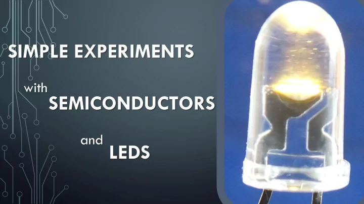

SIMPLE EXPERIMENTS with SEMICONDUCTORS and LEDS 1
THE CHANGE IN RESISTANCE OF Ge-CRYSTAL We need: • multimeter • slice of Ge • an insulating underlay, • two joiners through which we link the Ge-crystal with the multimeter • tweezers 2
• You place the slice of Ge on the insulating underlay then you fix the joiners carefully. 3
• The multimeter is switched into resistance measurement mode and the wires are connected accordingly. • The multimeter measurement limit is set in the resistance measurement range of 20 M Ω -inch measuring range. • At room temperature the instrument indicates a 14.51 M Ω resistor. 4
THE CHANGE IN THE Ge-CRYSTAL RESISTANCE DUE TO TEMPERATURE • When you heat the crystal with a hairdryer the resistance value decreases from 14.51 M Ω to 8.93 M Ω . 5
THE CHANGE IN THE RESISTANCE OF THE Ge-CRYSTAL UNDER LIGHT • The slice of Ge is illuminated with a 25- watt bulb. • The Ge resistance decreases due to the light, the instrument displays 5.25 M Ω resistor. 6
THE LED AS A CIRCUIT ELEMENT • Forward direction • The anode is connected to the positive potential, • the cathode is connected to the negative potential. • The current flows through the diode • The LED lights 7
• Reverse direction • the anode is connected to the negative potential,. • the cathode is connected to the positive potential • in the photo we changed the polarity of the voltage source. • There is no current in the circuit • The LED does not light up 8
THE LED WILL CONDUCT ELECTRICITY IN ONLY ONE DIRECTION • The LED will be connect to the direct current power supply with the help of a long wire. • The LED lights up only in case of forward direction. 9
• The LED rotated on the wire draws a continuous "circle of light". 10
• The LED is connected to alternating power supply with a long wire. • Apparently the LED lights well. 11
• THE LED ROTATED ON THE WIRE DRAWS A DASHED LIGHT CIRCLE On the move it is perceptible that the LED in fact lights only in the half period of the alternating voltage of forward direction. 12
THE ELECTRIC FIELD CAN BE SCANNED BY THE LED • Devices needed: • Slightly wet sand in a bowl • Two metal electrodes • LED 2 cm Its legs are bent in 2 cm • Direct current power supply • Voltage meter • Rulers • Wires 13
THE EXPERIMENT • On the top of the sand U ≈ 30 V direct current voltage is switched on electrodes placed in parallel in a distance of 10 cm. • In the wet sand surface layer nearly a homogeneous electric field is formed. • The LED stuck in the sand lights depending on how much and what kind of polarity voltage there is between its bent legs. 14
15
• Forward direction polarity n p U ≈ 30 V 10 cm ∙ 2 cm ≈ 6 V - + 2 cm • The LED lights brightly. 16
17
18
• Forward direction polarity - p U ≈ 30 V 10 cm ∙ 1,4 cm ≈ 4,2 V + n • The LED lights well. 1,4 cm 19
20
21
• Forward direction polarity U ≈ 30 V 10 cm ∙ 0,7 cm ≈ 2,1 V • The LED barely lights. 0,7 cm 22
23
• Legs of LED are standing on an equipotent line U ≈ 0 V • The LED does not light up. 24
• Reverse direction polarity U < 0 V • The LED does not light up. 25
• Reverse direction polarity U ≈ −6 V • The LED does not light up. 26
ILLUSTRATION OF THE OPERATION OF THE GRAETZ RECTIFIER CIRCUIT • The bar magnet moved through the coil induces alternating voltage • In the circuit diodes are lit, for which the current tension is in forward direction. 27
PRACTICAL APPLICATION OF GRAETZ CIRCUIT The motor always turns in the same direction owing to rectification Comment: We use a 3-volt motor 28
THE LED AS A VOLTAGE SOURCE • The LED terminals are switched to a voltmeter • The multimeter measures in the DC voltage range of 20 V at the measuring range. • In daytime lights the instrument shows 0.05 volts. 29
• The LED is illuminated by another LED from above. • Among the electrodes of the illuminated LED voltage increases. • The measured voltage by varying the intensity of illumination (approaching and removing LEDs) changes. The LED and the solar cell work similarly. 30
Recommend
More recommend