
SLIDE 1
1 Detectors for Nuclear and Particle Physics
Scintillation Counters
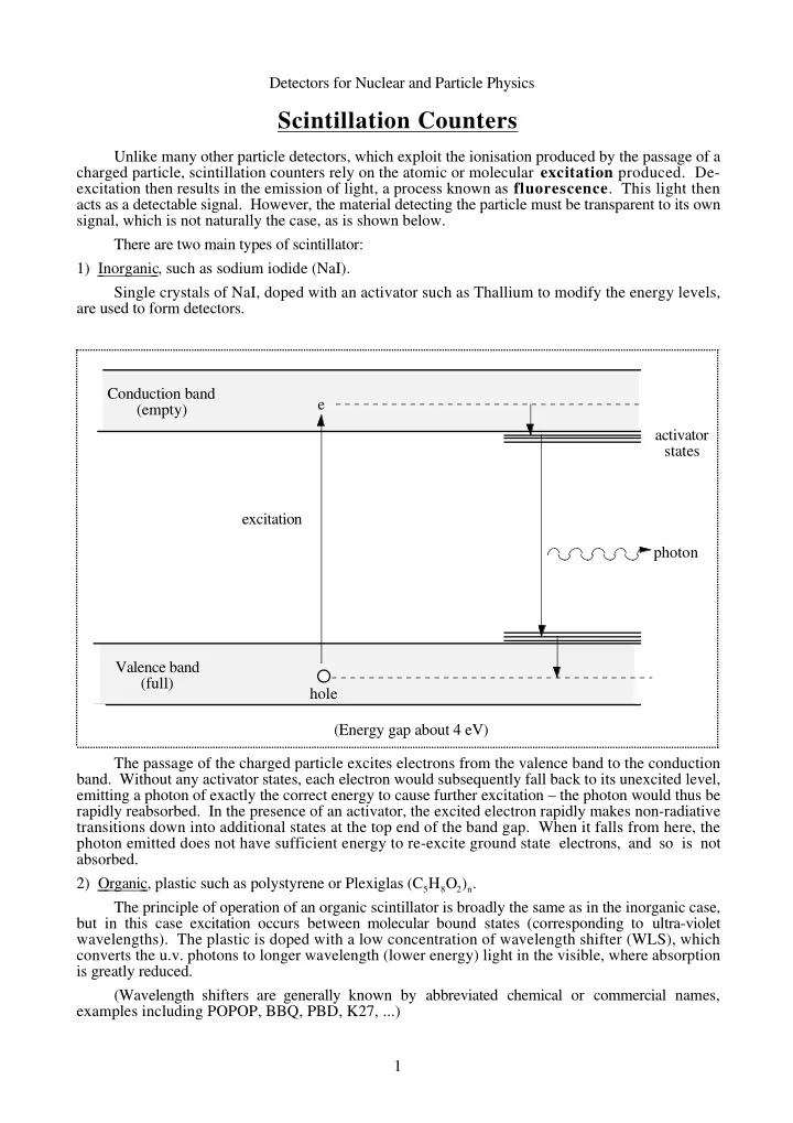
Unlike many other particle detectors, which exploit the ionisation produced by the passage of a charged particle, scintillation counters rely on the atomic or molecular excitation produced. De- excitation then results in the emission of light, a process known as fluorescence. This light then acts as a detectable signal. However, the material detecting the particle must be transparent to its own signal, which is not naturally the case, as is shown below. There are two main types of scintillator: 1) Inorganic , such as sodium iodide (NaI). Single crystals of NaI, doped with an activator such as Thallium to modify the energy levels, are used to form detectors. Conduction band (empty) Valence band (full) e hole excitation activator states photon (Energy gap about 4 eV) The passage of the charged particle excites electrons from the valence band to the conduction
- band. Without any activator states, each electron would subsequently fall back to its unexcited level,