Counter/Timers Overview ATmega328P has two _____ and one ______ - - PowerPoint PPT Presentation

counter timers overview
SMART_READER_LITE
LIVE PREVIEW

Counter/Timers Overview ATmega328P has two _____ and one ______ - - PowerPoint PPT Presentation

13.1 13.2 Counter/Timers Overview ATmega328P has two _____ and one ______ counters. Can configure to count at some frequency up to some value (a.k.a. ________________), generate an _____________ Unit 13 Timers and Counters and


slide-1
SLIDE 1

13.1

Unit 13 – Timers and Counters

13.2

Counter/Timers Overview

  • ATmega328P has two _____ and one ______ counters.

– Can configure to count at some frequency up to some value (a.k.a. ________________), generate an _____________ and ___________________ counting again, if desired – Useful for performing operations at specific time intervals. Every time an interrupt occurs, do something. – Can be used for other tasks such as pulse-width modulation (covered in future lectures)

  • But don't we already have delay()…why do we need

timers?

– So that we can do _________________________ while we are waiting for time to elapse!

13.3

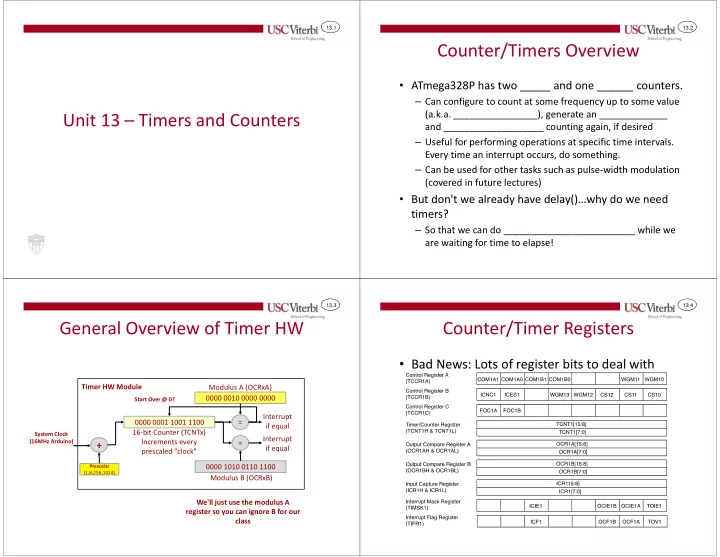
General Overview of Timer HW

0000 0001 1001 1100 16-bit Counter (TCNTx) Increments every prescaled "clock" = 0000 0010 0000 0000 Modulus A (OCRxA) = 0000 1010 0110 1100 Modulus B (OCRxB) Interrupt if equal Interrupt if equal

Start Over @ 0? System Clock (16MHz Arduino)

÷ ÷ ÷ ÷

Prescalar (1,8,256,1024)

Timer HW Module We'll just use the modulus A register so you can ignore B for our class

13.4

Counter/Timer Registers

  • Bad News: Lots of register bits to deal with
slide-2
SLIDE 2

13.5

Counter/Timer Registers

  • Good News: Can _______________ for simple timing

13.6

Computing the Desired Cycle Delay

  • Primary step: calculate how many processor

_________________ are required for your desired delay

– Desired clock cycles = ________________ × ______________ – Arduino UNO clock is fixed at 16 MHz

  • Example: 0.25 second delay with a 16 MHz clock

– Desired clock cycles = 16,000,000 c/s × 0.25s = _____________ cycles

  • Problem: The desired value you calculate must fit in at

most a __________________ (i.e. max _________)

– If the number is bigger than 65,535 then a prescalar must be used to reduce the clock frequency to the counter from 16MHz to something slower

13.7

Calculating the Prescalar

  • The counter prescaler divides the processor clock down to a

lower frequency so the counter is counting ______________.

  • Can divide the processor clock by four different powers of

two: _____, _______, ________, or _________.

  • Try prescalar options until the cycle count fits in 16-bits

– 4,000,000 / 8 = 500,000 – 4,000,000 / 64 = 62,500 – 4,000,000 / 256 = 15,625 – 4,000,000 / 1024 = 3906.25

  • In this example, either of the _____________ could work but

since we can only store integers in our timer count registers the last one would not yield exactly 0.25s (more like 0.249984s)

13.8

Counter/Timer Initialization 1

  • Set the mode for “Clear Timer on Compare” (CTC)

– WGM13 = ________, WGM12 = __________ – This tells the hardware to _______________ at 0

  • nce the counter is reaches your desired value
  • Enable “Output Compare A Match Interrupt”

– OCIE1A = 1

  • Load the 16-bit counter modulus into ___________

– This is the value the counter will count up to and then generate an interrupt. – The counter then clears to zero and starts counting up again. – In C, the register can be accessed as…

  • A 16-bit value "OCR1A"
  • Or as two eight bit values "OCR1AH" and OCR1AL”.

// Set to CTC mode TCCR1B |= (1 << WGM12); // Enable Timer Interrupt TIMSK1 |= (1 << OCIE1A); // Load the MAX count // Assuming prescalar=256 // counting to 15625 = // 0.25s w/ 16 MHz clock OCR1A = 15625;

slide-3
SLIDE 3

13.9

Counter/Timer Initialization 2

  • Select the prescalar value with bits:

CS12, CS11, CS10 in TCCR1B reg.

– 000 = stop ⟸ Timer starts when prescaler set to non-zero – 001 = clock/1 – 010 = clock/8 – 011 = clock/64 – 100 = clock/256 – 101 = clock/1024

  • Enable _________________________

// Set to CTC mode TCCR1B |= (1 << WGM12); // Enable Timer Interrupt TIMSK1 |= (1 << OCIE1A); // Load the MAX count // Assuming prescalar=256 // counting to 15625 = // 0.25s w/ 16 MHz clock OCR1A = 15625; // Set prescalar = 256 // and start counter TCCR1B |= (1 << CS12); // Enable interrupts sei(); 13.10

Counter/Timer Initialization 3

  • Make sure you have an appropriate

ISR function defined

– Using name ISR(TIMER1_COMPA_vect)

#include <avr/io.h> #include <avr/interrupt.h> volatile unsigned char qsecs = 0; void init_timer1(unsigned short m) { TCCR1B |= (1 << WGM12); TIMSK1 |= (1 << OCIE1A); OCR1A = m; TCCR1B |= (1 << CS12); } int main() { init_timer1(15625); sei(); while(){ // do something w/ qsecs } return 0; } ISR(TIMER1_COMPA_vect){ // increments every 0.25s qsecs++; } 13.11

8-bit Counter/Timers

  • The other two counters are similar but only 8-bits.
  • Same principle: find the count modulus that fits in an

8-bit value.

13.12

ISR Names

  • In CTC mode, an "Output Compare A Match

Interrupt" will vector to an ISR with these names:

– ISR(TIMER0_COMPA_vect) { } /* 8-bit Timer 0 */ – ISR(TIMER1_COMPA_vect) { } /* 16-bit Timer 1 */ – ISR(TIMER2_COMPA_vect) { } /* 8-bit Timer 2 */

slide-4
SLIDE 4

13.13

USING STATE MACHINES TO SIMPLIFY & ORGANIZE DESIGNS

Stopwatch Lab

13.14

An Example

  • Let's design a stopwatch (_______ units)
  • What are the inputs and outputs
  • Inputs

– Buttons for ______________ – ____________________

  • Outputs

– LCD [___________ time format]

  • Question:

– What do I need state for in this design?

  • Answer:

– Anytime you provide the same input and different outputs/actions occur, there is state inside – Different actions for same button press

Start/Stop (Top Btn) Lap/Reset (Bottom/Btn)

13.15

Why Use State Machines

  • It can be very hard/difficult to design a system

where all the inputs can __________ each of the outputs (i.e. an all-to-all relationship)

Timer Button1 Button 2 Other Output LCD

13.16

Why Use State Machines

  • Easier to decouple relationship between input and output
  • Let inputs _________________, then examine the state to

decide what ________________ should be or do

  • Similar to the popular MVC GUI & Web app design approach

– Model->View->Controller (MVC design) – Model (State), View (Output), Controller (Input)

Timer Button1 Button 2 Other Output LCD State

slide-5
SLIDE 5

13.17

Stopwatch Application

  • What states do we need to differentiate button presses
  • When timer interrupt occurs examine the state to decide how

to update the display (or just leave current displayed time)

  • What else in this design is technically "state"?

– Time: SS.Tenths – Every time the timer interrupts check to see if time needs to update & increment the time if necessary Stopped Started Lapped

Start_Stop Btn. Lap_Reset Start_Stop Btn. On Startup Lap_Reset || Start_Stop Lap_Reset / Set_to_Zero

13.18

Suggested Guidelines

  • Use a timer to generate an

interrupt every 0.1s

  • Use the timer ISR to

perform ____________ and ______________

  • Use __________ in main()

to detect input button presses and update state (but not necessarily display unless necessary)

... int main() { // be sure to init. state unsigned char state = 0; // init and start timer // used to check inputs // and perform state updates while(1) { // Poll inputs and update // state } return 0; } // Use to perform output tasks ISR(TIMER1_COMPA_vect) { // update time and // display based on state }