
SLIDE 1
C.1
Unit C – Timers and Counters
C.2
Counter/Timers Overview
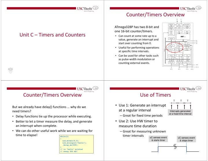
ATmega328P has two 8-bit and
- ne 16-bit counter/timers.
- Can count at some rate up to a
value, generate an interrupt and start over counting from 0.
- Useful for performing operations
at specific time intervals.
- Can be used for other tasks such
as pulse-width modulation or counting external events.
C.3
Counter/Timers Overview
But we already have delay() functions … why do we need timers?
- Delay functions tie up the processor while executing.
- Better to let a timer measure the delay, and generate
an interrupt when complete.
- We can do other useful work while we are waiting for
time to elapse!
while(1) { lcd_moveto(0,0); lcd_stringout("hello"); _delay_ms(500); } // is "hello" printed // every 500 ms?
C.4
Use of Timers
- Use 1: Generate an interrupt
at a regular interval
– Great for fixed time periods
- Use 2: Use HW timer to
measure time duration
– Great for measuring unknown timer intervals
uC senses event & starts timer uC senses event & stops timer Interrupts generated at a fixed time interval T T T