ROUTING vs. FORWARDING www.sorin-schwartz.com ROUTERS EVOLUTION - - PowerPoint PPT Presentation

routing vs forwarding
SMART_READER_LITE
LIVE PREVIEW

ROUTING vs. FORWARDING www.sorin-schwartz.com ROUTERS EVOLUTION - - PowerPoint PPT Presentation

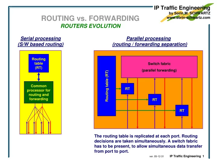
IP Traffic Engineering by Sorin M. SCHWARTZ ROUTING vs. FORWARDING www.sorin-schwartz.com ROUTERS EVOLUTION Serial processing Parallel processing (S/W based routing) (routing / forwarding separation) Routing table Switch fabric (RT)


slide-1
SLIDE 1

IP Traffic Engineering

by Sorin M. SCHWARTZ www.sorin-schwartz.com

  • ver. 05-12-31

IP Traffic Engineering 1

ROUTING vs. FORWARDING

ROUTERS EVOLUTION

Serial processing (S/W based routing) Parallel processing (routing / forwarding separation)

Routing table (RT) Common processor for routing and forwarding Routing table (RT) Switch fabric (parallel forwarding) RT RT RT

The routing table is replicated at each port. Routing decisions are taken simultaneously. A switch fabric has to be present, to allow simultaneous data transfer from port to port.

slide-2
SLIDE 2

IP Traffic Engineering

by Sorin M. SCHWARTZ www.sorin-schwartz.com

  • ver. 05-12-31

IP Traffic Engineering 2

ROUTING vs. FORWARDING

ROUTERS EVOLUTION

Label switching

RT RT RT Routing table (RT) Switch fabric (parallel forwarding) Routing table (RT) Switch fabric (parallel forwarding) Routing table (RT) Switch fabric (parallel forwarding) add LABEL remove LABEL

Concepts

  • Ingress router adds a label
  • Core routers identify the label and forward to apriori decided port (next hop)
  • Egress router removes the label
  • Assumptions
  • The route to be followed has been decided in an independent process that occurred

before the network operation

  • Routers have bindings between specific labels and specific, apriori decided routes to be

followed by packets marked with that labels

slide-3
SLIDE 3

IP Traffic Engineering

by Sorin M. SCHWARTZ www.sorin-schwartz.com

  • ver. 05-12-31

IP Traffic Engineering 3

MULTIPROTOCOL LABEL SWITCHING (MPLS)

BASIC OPERATION

Label stacking

Rb Rd X

LSR 3 LSR 4 LSR 7 LSR 1

Ra Re MPLS cloud Q

LSR 5 1 2 3 1 2 LSR 6

Y

IP DA = Y payload

P

L211

IP DA = Y payload

1 LSR 2 1 2 L652

IP DA = Y payload

L411

IP DA = T payload

T S

L161

IP DA = payloa Y d

L363 L162

IP DA = T payload

L363 L672

IP DA = T payload

LSR6 tables

FEC NHLFE (Next Hop Label Forwarding Entry)

  • (-)
  • (-)

FTN (FEC-To-NHLF)

NHLFE (1) (2) next hop LSR5 LSR7

  • peration

label swap label swap label L651 L671 physical interface 1 2

NHLF (Next Hop Label Forwarding)

label NHLFE (Next Hop Label Forwarding Entry) 361 (1) 362 (2)

ILM (Incoming Label Map)

363 (3) (3)

  • label pop

L363

  • 161

(4) (4) LSR5 label swap L652 1 162 (5) (5) LSR7 label swap L672 2

slide-4
SLIDE 4

IP Traffic Engineering

by Sorin M. SCHWARTZ www.sorin-schwartz.com

  • ver. 05-12-31

IP Traffic Engineering 4

MULTIPROTOCOL LABEL SWITCHING (MPLS)

LABEL ENCODING

Identifying labeled packets

  • Layer 2 header is written following the rules in effect between the sending LSR and the receiving next

hop LSR

  • The receiving LSR should identify the packet as a “labeled” one, as opposed to a non-labeled packet

which could arrive on the same link

DA

Layer 2 header Ethernet

SA

Layer 3 header IP + …

Type = IP S LABEL EXP TTL DA

Layer 2 header Ethernet

SA Type = MPLS

Layer 3 header IP + …

1

MPLS label presence is indicated by new Ethertypes

  • hex 8847 (dec 34,887) - MPLS unicast
  • hex 8848 (dec 34,888) - MPLS multicast

(To be used with LLC/SNAP/OUI 000000, too)

DA

Layer 2 header Ethernet

SA

Layer 3 header ?? + …

Type = ??

After removing the last label, the packet should be processed based on its original layer 3 header, but the information related to layer 3 protocol in the original packet is lost! LSR should be able to identify original layer 3 protocol for internal processing and for the generation of the packet to be sent to the next hop.

LSR 1 LSR 2

slide-5
SLIDE 5

IP Traffic Engineering

by Sorin M. SCHWARTZ www.sorin-schwartz.com

  • ver. 05-12-31

IP Traffic Engineering 5

Virtual Private Networks

LAYER 3, BGP/MPLS based VPN

CEd NET1 PE 2 PE 3 P6

site 2 site 4 site 1 site 3 site 5

CEa NET2 PE 1

site 6 site 7

CEg NET3 PE 4 P5 P7 CEc NET4 L57 L15 P5 PE1 CE b CE a

VRF site 2 VRF site 4 BGP tables IGP and MPLS tables

PE4 CEf CE g

VRF site 6 VRF site 7 BGP tables IGP and MPLS tables IGP and MPLS tables

P7

IGP and MPLS tables IGP LDP IGP LDP IGP LDP

CEe NET2 CEf NET3 CEb NET1

Step 6

  • PE4 has “VRF site6”

export route target “VPN RED”

  • PE1 has “VRF site2” import

route target “VPN RED”, so it will accept the MP-iBGP update arriving from PE4

  • PE1 updates its “VRF

site2” table

Basic operation - Routing information exchange

(simplified) MP-iBGP session

PE1 “VRF site2” routing table

To destination net3 Deliver to router PE4 int’f FEC site6:net3 (L63)

PE1 BGP routing table

To destination site6:net3 Deliver to router PE4 int’f FEC site6:net3 (L63)

PE1 IGP routing table

To destination PE4 Deliver to router PE4 nr of hops physical interface FEC a / L15

slide-6
SLIDE 6

IP Traffic Engineering

by Sorin M. SCHWARTZ www.sorin-schwartz.com

  • ver. 05-12-31

IP Traffic Engineering 6

Virtual Private Networks

IP Sec based VPN

Authentication and Integrity Check principles

Generating and Using the ICV - Transmission process

  • For calculation purposes only, the ICV field value is set to “0”
  • For calculation purposes only, fields expected to change during

the travel through the network are set to “0” (e.g. time to live) variable length input data

Original packet before authentication process (IP header + payload)

Authentication Field

ICV Original packet (IP header + payload) hash function

encryption key MAC fixed length

  • utput data

(128 or 160 bits)

SHA-1 MD5 DES 3DES HMAC-SHA-1-96 HMAC-MD5-96 encryption function

Packet with added authentication fields , including ICV field (sent to the other site)

ICV (Integrity Check Value) is the result of two consecutive processes executed over the packet to be protected:

  • step 1 - A hash value is

calculated for the packet to be protected. The hash function is not a secret.

  • step 2 - The hash value
  • btained in step 1 is

encrypted using a secret key, generating the ICV value to be added to the packet. The encrypted hash value (the MAC) can be correctly decoded ONLY by the SAME secret key, at reception side.