
UMTS and LTE
1
References
¨ Material Related to LTE comes from ¤ “3GPP LTE: System Overview, Product Development
and Test Challenges,” Agilent Technologies Application Note, 2008.
¤ IEEE Communications Magazine, February 2009 ¤ IEEE Communications Magazine, April 2009 ¤ Bell Labs Technical Journal, Vol. 13, No. 4, 2009 ¤ LTE: The UMTS Long Term Evolution, Ed. S. Sesia et al,
John Wiley and Sons, 2011
2
What is UMTS?
¨ UMTS stands for Universal Mobile Telecommunications System ¤ 3G cellular standard in the US, Europe, and Asia ¨ Outcome of several research activities in Europe ¤ Assisted the standardization efforts ¨ Most of the standardization work was focused in 3GPP (3rd Generaration
Partnership Project)
¤ 3GPP refers to the physical layer as UTRA – UMTS Terrestrial Radio Access ¤ There are two modes – FDD and TDD 3
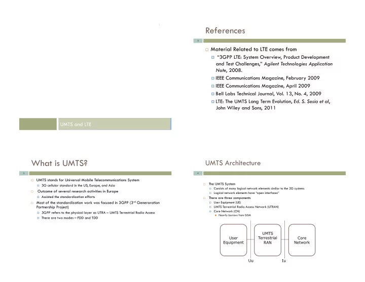
UMTS Architecture
¨ The UMTS System ¤ Consists of many logical network elements similar to the 2G systems ¤ Logical network elements have “open interfaces” ¨ There are three components ¤ User Equipment (UE) ¤ UMTS Terrestrial Radio Access Network (UTRAN) ¤ Core Network (CN) n Heavily borrows from GSM
4
User Equipment UMTS Terrestrial RAN Core Network Uu Iu