REAL-TIME IMPACT FORCE IDENTIFICATION OF CFRP LAMINATED PLATES USING - - PDF document

real time impact force identification of cfrp laminated
SMART_READER_LITE
LIVE PREVIEW

REAL-TIME IMPACT FORCE IDENTIFICATION OF CFRP LAMINATED PLATES USING - - PDF document

18 TH INTERNATIONAL CONFERENCE ON COMPOSITE MATERIALS REAL-TIME IMPACT FORCE IDENTIFICATION OF CFRP LAMINATED PLATES USING SOUND WAVES S. Atobe 1* , H. Kobayashi 2 , N. Hu 3 and H. Fukunaga 1 1 Department of Aerospace Engineering, Tohoku


slide-1
SLIDE 1

18TH INTERNATIONAL CONFERENCE ON COMPOSITE MATERIALS

1 Introduction Impact force identification of CFRP laminated plates has received wide attention because laminates have a low tolerance to transverse impact forces. In the case

  • f aerospace structures, impacts by foreign objects,

such as hail, birds and tools, induce impact damage and degrade the mechanical properties of the CFRP

  • structure. In such a case, the identification results of

the impact location and force history give significant information which could be used to predict the impact damage. Methods for identifying impact forces have been reported by many researchers thus far [1]. Generally, sensors that are used to measure the responses of the structure are those that can be bonded or embedded, such as strain gauges [2], accelerometers [3], piezo- electric sensors [4] and FBG sensors [5]. However, bonded or embedded sensors may complicate the manufacturing and maintenance processes. From a practical point of view, a method which identifies the impact force using the measured data obtained from noncontact sensors, such as microphones [6, 7], is considered to be more effective. This paper proposes a method to identify the location and force history of an impact force acting

  • n CFRP laminated plates using the radiated sound.

The impact location is identified using arrival times

  • f the sound wave at the microphones. Force history

is identified based on experimental transfer matrices which relate the impact force and the measured sound pressures. In order to verify the validity of the proposed method, impact force identification of a CFRP laminated plate is performed experimentally, and the identification results are compared with the measured ones. In addition, the effect of the stiffness

  • f the impactor on the accuracy of identification

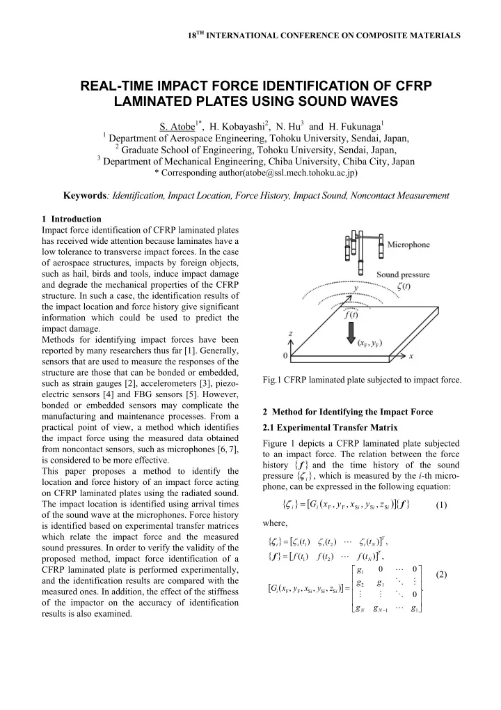
results is also examined. Fig.1 CFRP laminated plate subjected to impact force. 2 Method for Identifying the Impact Force 2.1 Experimental Transfer Matrix Figure 1 depicts a CFRP laminated plate subjected to an impact force. The relation between the force history { } f and the time history of the sound pressure { }

i

ζ , which is measured by the i-th micro- phone, can be expressed in the following equation:

{ } ( ) [ ]{ }

f

i i i i i

z y x y x G

S S S F F

, , , , = ζ (1) where, { } [ ] { } [ ] ( ) [ ]

. , , , , , ) ( ) ( ) ( , ) ( ) ( ) (

1 1 1 2 1 S S S F F 2 1 2 1

            = = =

g g g g g g z y x y x G t f t f t f t t t

N N i i i i T N T N i i i i

L O M M M O L L L f ζ ζ ζ ζ

(2)

REAL-TIME IMPACT FORCE IDENTIFICATION OF CFRP LAMINATED PLATES USING SOUND WAVES

  • S. Atobe1*, H. Kobayashi2, N. Hu3 and H. Fukunaga1

1 Department of Aerospace Engineering, Tohoku University, Sendai, Japan, 2 Graduate School of Engineering, Tohoku University, Sendai, Japan, 3 Department of Mechanical Engineering, Chiba University, Chiba City, Japan

* Corresponding author(atobe@ssl.mech.tohoku.ac.jp)

Keywords: Identification, Impact Location, Force History, Impact Sound, Noncontact Measurement

slide-2
SLIDE 2

Here, ) ( n

i t

ζ and ) ( n t f are the sound pressure and force at time

s

t n tn ∆ = ) , , 1 ( N n K = , respectively,

s

t ∆ is the sampling time, and [

]

i

G is a transfer matrix composed of the Green’s function. It is worthwhile to note that the transfer matrix is defined by a function of the impact location ) , (

F F y

x and sensor location ) , , (

S S S i i i

z y x , and is not dependent

  • n the force history.

The transfer matrix is determined experimentally using the measured data obtained from impact tests conducted by an impulse hammer [8]. By trans- forming Eq.(1), we obtain

{ } [ ]{ }

i i

F g = ζ (3) where, [ ] { } [ ] .

, ) ( ) ( ) ( ) ( ) ( ) (

2 1 1 1 1 2 1 T N i N N

g g g t f t f t f t f t f t f F L L O M M M O L =             =

g

(4) The components of the transfer matrix { }

i

g are determined so that the estimated sound pressure, which is given by Eq.(3) using the measured force history, is adjusted to the measured one. In order to reduce the effect of measurement error, the measured data are obtained by conducting impact tests K times. Thus, the components are determined by solving the optimization problem as follows:

{ }

{ } [ ]

{ } .

: minimize

1 2

=

K k i k k i

F

i

g

g

ζ (5) Here, the least-squares method is used to solve Eq.(5). (a) (b) Fig.2 Interpolation of transfer matrix. As a preparatory work for impact force identification, construction of the experimental transfer matrices is

  • undertaken. The identification region is divided into

discrete areas, as shown in Fig.2 (a), and impact tests are conducted at every node. Then, the experimental transfer matrices are determined for each combi- nation of node and sensor by employing Eq.(5). Inside four nodes in each area, the transfer matrix is interpolated using shape functions similar to those used in finite element analyses. When a four-node two-dimensional element is used, as depicted in Fig.2 (b), the transfer matrix interpolation is expressed as:

( ) [ ] ( ) [ ]

i i i l l i l l i i i i

z y x y x G N z y x y x G

S S S 4 1 S S S F F

, , , , , , , ,

=

× = (6) where

( )( ) ( )( ) ( )( ) ( )( ).

1 1 4 1 , 1 1 4 1 , 1 1 4 1 , 1 1 4 1

F F 4 F F 3 F F 2 F F 1

η ξ η ξ η ξ η ξ + − = + + = − + = − − = N N N N

(7) Here, ) , (

l l y

x are the coordinates of node l, and ) , (

F F η

ξ

are the normalized coordinates of the impact location. 2.2 Impact Location Identification The impact location is identified using the difference in the arrival times of the sound waves. The

  • ptimization problem solved in the impact location

identification is as follows:

( )

∑ ∑

− = + =

      − − ∆

1 1 1 2 ,

) ( 1 : minimize

F F

I i I i j i j ij y x

r r v t (8) Here, ∆tij is the difference in the arrival times at the i-th and j-th microphones, r is the distance between the impact location and the microphone, and v is the speed of sound in the air. In order to solve the optimization problem of Eq.(8), the conjugate gradient method with golden section method is used. 2.3 Force History Identification The force history is identified by minimizing the deviation between the measured sound pressures and the estimated ones using the experimental transfer

  • matrices. Then, the identification problem reduces to
slide-3
SLIDE 3

REAL-TIME IMPACT FORCE IDENTIFICATION OF CFRP LAMINATED PLATES USING SOUND WAVES 3

an optimization problem that is formulated as follows:

{ }

{ } [ ]{ }

) ( : subject to : minimize

1 2

≥ −

=

t f G

I i i i

f

f

ζ (9) In order to solve the optimization problem of Eq.(9), the quadratic programming method is used. 3 Experimental Results and Discussion 3.1 Experimental Setup The dimensions of the CFRP laminated plate are

mm 2 mm 300 mm 300 × ×

, and the laminate sequence is [ ]s

2 2 2 2

90 45 45 − . As to the boundary conditions, the plate is clamped at the corners by jigs with a 35mm square area. The schematic of the experimental setup is shown in Fig.2. Impact force is applied to the plate by an impulse hammer (Ono Sokki GK-3100), and the radiated sound is measured by four microphones (Ono Sokki MI-1234). The signal from the microphone is amplified by a preamplifier and a sensor amplifier (Ono Sokki MI-3111, SR-2200), and the sound pressure is recorded by a digital

  • scilloscope (Keyence GR-7000). Simultaneously,

the force obtained from the impulse hammer is also

  • measured. Then, impact force identification is

performed by a computer using the acquired data. The locations of the microphones are indicated in Table 1. As to the impact tip of the impulse hammer, two types of tips, one made of hard plastic (hard tip) and the other made of rubber (soft tip), are used. The force history and the corresponding sensor responses are measured in the time period of 14ms and the sampling time is set to s 20

s

µ = ∆t

.

The identification region is a 120mm square area, whose center coincides with that of the plate. In determining the experimental transfer matrices, the identification region is equally divided into six in the directions of the x and y axes, as shown in Fig.2 (a). Then, the number of nodes where the transfer matrices are determined is 49. The number of impact tests conducted for each node is 5 = K . In the present study, two types of transfer matrices are constructed by changing the impact tip used in the impact tests. Fig.2 Experimental setup Table 1 Sensor locations Microphone ) , , (

S S S i i i

z y x No.1 ) 248 , 150 , 150 ( No.2 ) 297 , 150 , 185 ( No.3 ) 297 , 180 , 133 ( No.4 ) 297 , 120 , 133 ( 3.2 Identification Results and Discussion The identification results of impact location are shown in Fig.3. Identification was performed at 36 points, and by applying the force using the two impact tips. As can be seen from the figure, the identified locations are in good agreement with the measured ones. The locations were identified within the error of 8.91mm in the case of the soft tip, and 4.91mm for the hard tip. The identification results reveal that the impact location is identified accurately by the proposed method, and that the accuracy is independent of the stiffness of the impactor. Table 2 shows the experimental conditions of the force history identification. The identification is divided into four cases depending on the impact tips which were used for the construction of the transfer matrices and for the identification test. Figure 4 shows the identification results of the force history

  • f an impact force applied by the soft tip. The impact

location corresponds to point A in Fig.3 (a), which is the point whose error of the identified location is the

  • maximum. The figure reveals that the force history
  • f the soft tip is identified with sufficient accuracy,

regardless of the type of impact tip used in the construction of the experimental transfer matrices. The identification results of force history for the hard

slide-4
SLIDE 4

(a) Soft tip (a) Case I Table 2 Experimental conditions of force history identification. Case Transfer matrix Identification I Soft tip Soft tip II Hard tip Soft tip III Hard tip Hard tip IV Soft tip Hard tip tip is shown in Fig.5. The identification results correspond to those of point B depicted in Fig.3 (b). The error of the identified location for point B is 4.91mm. As can be seen from Fig.5 (a), the identified (b) Hard tip (b) Case II Table 3 Error of identified force history. Error of identified force history (%) Case Minimum Maximum Average I 0.09 5.49 1.88 II 0.02 9.68 3.03 III 0.34 18.0 6.19 IV 4.64 65.7 30.7 force history shows good agreement with the measured one, although there is a small difference after the impact force is unloaded. On the other hand, in the case of Case IV which is shown in Fig.5 (b), Fig.3 Identification results of impact location. Fig.4 Results of force history identification of an impact force applied by soft tip (Point A).

slide-5
SLIDE 5

REAL-TIME IMPACT FORCE IDENTIFICATION OF CFRP LAMINATED PLATES USING SOUND WAVES 5

(a) Case III Fig.6 FFT results of measured sound pressure. the force history is not identified accurately. The error of the identified force history

F

E , which is defined by Eq.(10), is summarized in Table 3. ) ( ) ( ) (

MAX m m MAX m m MAX m i F

t f t f t f E − = (10) Here,

) (

i t

f and ) (

m t

f are the identified force and the measured force, respectively, and

MAX m

t is the time of the maximum measured force. The results reveal that impact force by the hard tip cannot be identified using experimental transfer matrices constructed with the soft tip. This is due to the difference in the frequency components of the radiated sound depending on the stiffness of the impactor. Figure 6 shows FFT results of the measured sound pressures for the two impact tips. In the case of the soft tip, the significant amplitudes are in the frequency range of less than 5kHz. On the other hand, in the case of the hard tip, the measured sound pressure contains (b) Case IV frequency components higher than 5kHz. Thus, experimental transfer matrices constructed with the soft tip cannot estimate the sensor responses accurately in the case of impact force by the hard tip. Therefore, in order to obtain sensor responses that have a wide frequency range, construction of the experimental transfer matrices should be conducted using a stiff impactor. The time required by the proposed method to identify the location and force history of an impact force was approximately 1 second. From a practical point of view, it can be said that the proposed method is capable of identifying the impact force in real time. 4 Conclusion In this paper, a method for identifying an impact force acting on a CFRP laminated plate has been

  • developed. The proposed method uses measured

sound pressures obtained by microphones to identify the location and force history. The validity of the proposed method has been verified experimentally. The results reveal that the location and force history can be identified in real time and accurately by the proposed identification method. In addition, it has been found that the accuracy of impact location identification is not dependent on the stiffness of the

  • impactor. The force history is also identified accurately

regardless of the stiffness of the impactor, when a hard tip is used in the impact tests conducted for the construction of the experimental transfer matrices. Fig.5 Results of force history identification of an impact force applied by hard tip (Point B)

slide-6
SLIDE 6

References

[1] H. Inoue, J.J. Harrigan and S.R. Reid “Review of inverse analysis for indirect measurement of impact force”. Applied Mechanics Reviews, Vol. 54, No. 6, pp 503-524, 2001. [2] E. Wu, J.C. Yeh and C.S. Yen “Identification of impact forces at multiple locations on laminated plates”. AIAA Journal, Vol. 32, No. 12, pp 2433-2439, 1994. [3] M. Sato, T. Onozaki, H. Sekine and H. Fukunaga “Proposition of simple identification method for multiple impact forces on orthotropic laminated plates”. Transactions of the Japan Society of Mechanical Engineers, A, Vol. 64, No. 627, pp 2677- 2685, 1998. (in Japanese) [4] M. Tracy and F.K. Chang “Identifying impacts in composite plates with piezoelectric strain sensors, Part I: Theory, Part II: Experiment”. Journal of Intelligent Material Systems and Structures, Vol. 9,

  • No. 11, pp 920-928, 929-937, 1998.

[5] H. Tsutsui, A. Kawamata, J. Kimoto, A. Isoe, Y. Hirose,

  • T. Sanda and N. Takeda “Impact damage detection

system using small-diameter optical-fiber sensors embedded in CFRP laminate structures”. Advanced Composite Materials, Vol. 13, No. 1, pp 43-55, 2004. [6] K. Sekiguchi, S. Kimura and T. Hanyuu “Analysis of sound field on spatial information using a four- channel microphone system based regular tetrahedron peak point method”. Applied Acoustics, Vol. 37, No. 4, pp 305-323, 1992. [7] T. Tsuji, Y. Kawada, Y. Suzuki, T. Yamaguchi and

  • N. Noda “Identification of an impact force by radiated

sound from the impacted body”. Transactions of the Japan Society of Mechanical Engineers, A, Vol. 65,

  • No. 632, pp 701-707, 1999. (in Japanese)

[8] S. Atobe, N. Hu and H. Fukunaga “Real-time impact force identification of CFRP structures using experimental transfer matrices”. Proceedings of the 14th US-Japan Conference on Composite Materials, Dayton, 1058, 2010.