
SLIDE 1
1
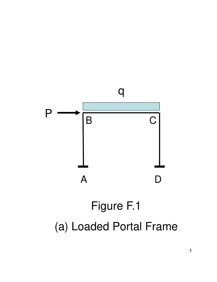
q P B C A D Figure F.1 (a) Loaded Portal Frame 1 BC BC M - - PDF document
q P B C A D Figure F.1 (a) Loaded Portal Frame 1 BC BC M M B C BC BC T T B C BC V BC V C B CD AB T T C B CD CD V M C AB C V B AB M B F.1 (b) AB CD V V A D AB CD M M A D AB CD T T 2 A D
1
2
3
4
5