
SLIDE 1
1
ProtoDUNE SP CPA and FC ProtoDUNE SP CPA and FC QA/QC Plan QA/QC - - PowerPoint PPT Presentation
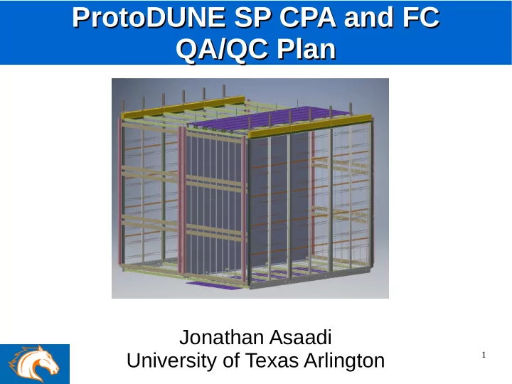
ProtoDUNE SP CPA and FC ProtoDUNE SP CPA and FC QA/QC Plan QA/QC Plan Jonathan Asaadi University of Texas Arlington 1 Overview Overview This talk is meant to convey some of the lessons learned from MicroBooNE and LArIAT This is
1
2
– Many of these tests are planned / being done / will
– Not a fully exhaustive list and will likely need to be
3
Large metal components for the field cage and cathode Soaking bath and rinse to remove grease and large pieces of F.O.D. Requires a place large enough to allow for cleaning and drying
assembly Drilled holes in all components Identifying and removing metal shavings, burrs, Need to check any internal components of large machined parts Small component (elbows, screws, etc) cleaning Ultra sonic bath soak Need to keep track of which components go where and repackaging after cleaning
4
– Rolled form field cage tubes – G10 I beams – Plastic Caps – etc…
– For MicroBooNE and LArIAT this required having
– Larger soaking baths (simple green cleaning
– Checking for metal burs, foreign object debris,
Soaking bath for MicroBooNE Soaking bath for MicroBooNE Field Cage Tubes Field Cage Tubes
5
MicroBooNE DocDB 2259 can be made available to help
6
Threaded components Application of anti-galling coating MicroBooNE used moly-coat sprayed on all bolts Interferences between mating components Ensuring the correct bolt/nut/washer is installed in the correct place There are often many very similar components and the need to have them (re)labeled following cleaning / coating and cataloged is important Identifying correct bolt head types Need E-Field studies for various types to minimize potential source for breakdown
7
– We had quite a few examples of
– Need to be careful of which bolts
– Will help with vendor availability – All the parts need to be cleaned,
Application of moly-coat to Application of moly-coat to MicroBooNE screws MicroBooNE screws E-field study for different E-field study for different bolt head components bolt head components
8
– On MicroBooNE and LArIAT we had a
– These were caught during later test
MicroBooNE TPC during MicroBooNE TPC during installation with very tight installation with very tight clearances clearances Similar enough bolt initially Similar enough bolt initially installed in the wrong position installed in the wrong position
9
Flatness of assembled cathode Survey test done during construction and following installation This can be a time consuming process, but can be an essential driver of the physics so needs to be accounted for Electrical connectivity between cathode components Resistive measurement (or possibly small current measurement) The application of resistive coating will likely require a bit more thought to verify electrical connection Tests of high voltage bus Stand-alone high voltage tests Assembled and installed cryo- tests The details of this component still remain a bit less clear to me...so the details of the tesing here are not thought out yet
10
MicroBooNE achieved a cathode flatness of MicroBooNE achieved a cathode flatness of +/- 6 mm over the 10.3 meter length +/- 6 mm over the 10.3 meter length
11
– These tests are likely best both
– Likely as part of the overall CPA
12
Test of individual resistor and varistor components High voltage tests to verify behavior and function Tests should be done warm and cold and results should be cataloged by components Matching components to ensure correct tube-to-tube resistance Resistive measurement (or possibly small current measurement) Test should be done warm and cold Resistors and varistor tests Spark tests and clamping behavior Done for MicroBooNE and LArIAT in the cold...but this was more for safety reasons Testing of the PCB board Destructive HV tests as well as baseline HV performance tests We found problems with the boards in LArIAT and had to go to directly soldering components onto the field cage
13
– A similar rig was used for
14
MicroBooNE DocDB 3397 provides details of the tests performed
15
Mechanical test fits to look for interferences High voltage tests to verify behavior and function This assumes the cryostat is ready before the detector is complete….but could be done before actual installation if the schedule allows Verify electrical conductivity of the cathode High voltage tests to verify behavior and function (Need to think how the resistive coating complicates this measurement) Verify the resistor divider network Apply ~1 kV to the cathode in incremental steps and check the current is as expected as well as verify the voltage near the APA
16
– TPC test fits – Electronics and PMT mounting
– Cable routing and interference
Mechanical fit tests done with Mechanical fit tests done with “dummy” motherboards on LArIAT “dummy” motherboards on LArIAT
TPC test fits and moch cable routing done TPC test fits and moch cable routing done with MicroBooNE and LArIAT with MicroBooNE and LArIAT
17
– Testing the current seen when
– Measuring the impedance
– Measuring the capacitance in the
MicroBooNE 1kV MicroBooNE 1kV test of the field test of the field cage network post cage network post installation installation
18
– Instead meant to help during the planning stage based on
– I am happy to help in the transformation of these
– New things will pop up during installation, but if you’ve