
CSCE 515:
Computer Network Programming
OSI Models & Data link layer
Wenyuan Xu Department of Computer Science and Engineering University of South Carolina
Some slides are made by Dave Hollinger and Badri Nath
CSCE515 – Computer Network Programming 2007
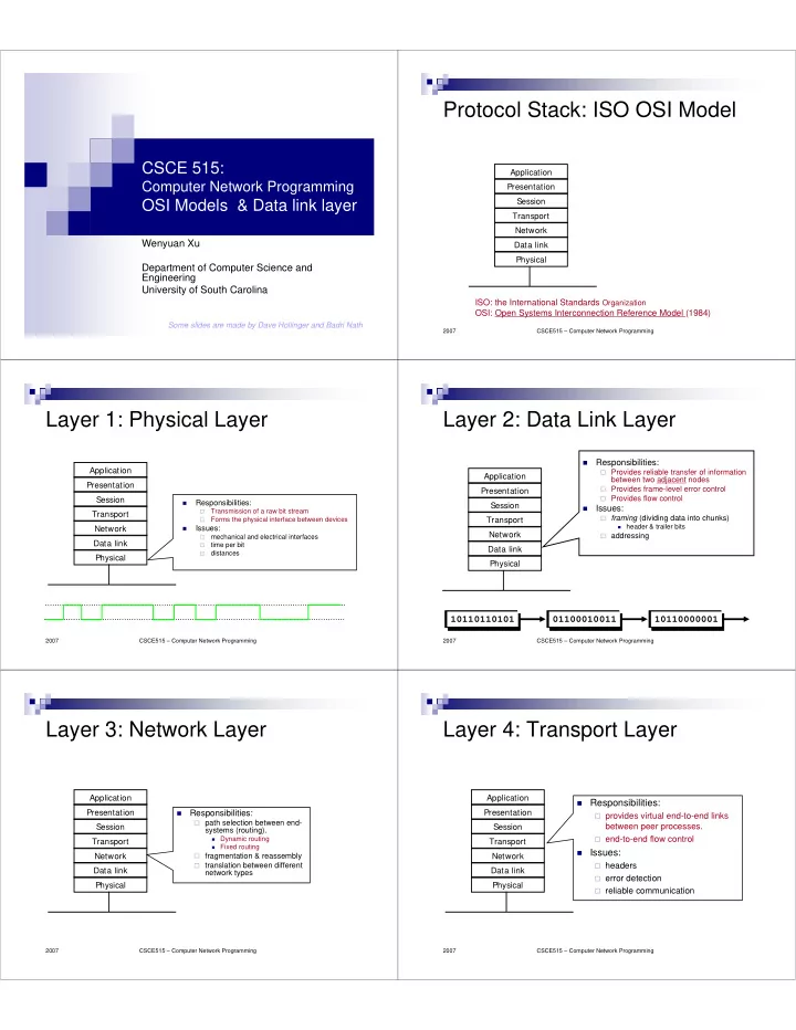
Protocol Stack: ISO OSI Model
Application Presentation Session Transport Network Data link Physical ISO: the International Standards Organization OSI: Open Systems Interconnection Reference Model (1984)
CSCE515 – Computer Network Programming 2007
Layer 1: Physical Layer
Application Presentation Session Transport Network Data link Physical
- Responsibilities:
- Transmission of a raw bit stream
- Forms the physical interface between devices
- Issues:
- mechanical and electrical interfaces
- time per bit
- distances
CSCE515 – Computer Network Programming 2007
Layer 2: Data Link Layer
Application Presentation Session Transport Network Data link Physical
- Responsibilities:
Provides reliable transfer of information
between two adjacent nodes
Provides frame-level error control Provides flow control
- Issues:
framing (dividing data into chunks)
- header & trailer bits
addressing
01100010011 10110000001 10110110101
CSCE515 – Computer Network Programming 2007
Layer 3: Network Layer
Application Presentation Session Transport Network Data link Physical
- Responsibilities:
path selection between end-
systems (routing).
- Dynamic routing
- Fixed routing
fragmentation & reassembly translation between different
network types
CSCE515 – Computer Network Programming 2007
Layer 4: Transport Layer
Application Presentation Session Transport Network Data link Physical
Responsibilities: provides virtual end-to-end links
between peer processes.
end-to-end flow control Issues: headers error detection reliable communication