
SLIDE 1
1
- Encoders, Decoders & Shifters
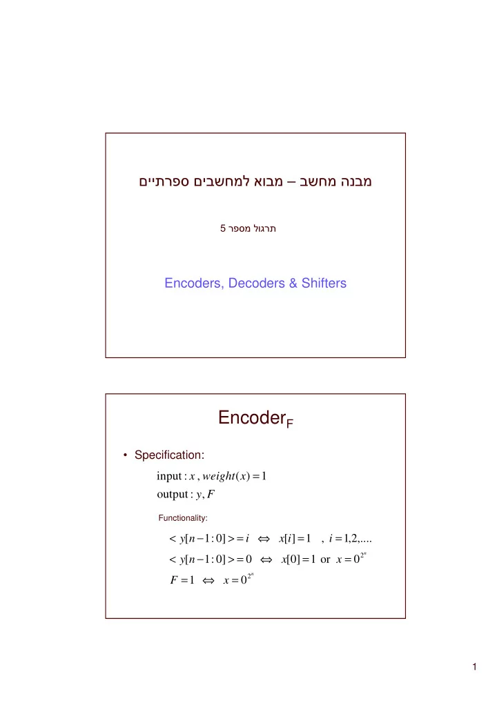
- EncoderF
- Specification:
F y x weight x , :
- utput
1 ) ( , : input =
n n
x F x x n y i i x i n y
2 2
1
- r
1 ] [ ] : 1 [ ,.... 2 , 1 , 1 ] [ ] : 1 [ = ⇔ = = = ⇔ = > − < = = ⇔ = > − <
Functionality: