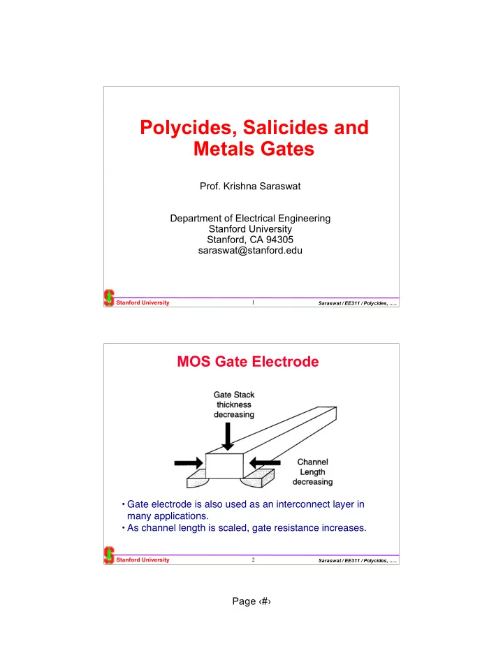
Polycides, Salicides and Metals Gates Prof. Krishna Saraswat - - PDF document

polycides salicides and metals gates
SMART_READER_LITE
LIVE PREVIEW

Polycides, Salicides and Metals Gates Prof. Krishna Saraswat - - PDF document

Polycides, Salicides and Metals Gates Prof. Krishna Saraswat Department of Electrical Engineering Stanford University Stanford, CA 94305 saraswat@stanford.edu Stanford University 1 Saraswat / EE311 / Polycides, .. MOS Gate Electrode


slide-1
SLIDE 1

Page ‹#›

Stanford University

Saraswat / EE311 / Polycides, …..

1

  • Prof. Krishna Saraswat

Department of Electrical Engineering Stanford University Stanford, CA 94305 saraswat@stanford.edu

Polycides, Salicides and Metals Gates

Stanford University

Saraswat / EE311 / Polycides, …..

2

MOS Gate Electrode

  • Gate electrode is also used as an interconnect layer in

many applications.

  • As channel length is scaled, gate resistance increases.
slide-2
SLIDE 2

Page ‹#›

Stanford University

Saraswat / EE311 / Polycides, …..

3

Effect of Scaling of Contacts and Junctions

Silicidation of junctions is necessary to minimize the impact of junction parasitic resistance

Ref: Ohguro, et al., ULSI Science and Technology 1997, Electrochemical Soc. Proc., Vol. 97-3

R (total) = Rch + Rparasitic Rparasitic = Rextension + Rextrinsic Rextension = Rd’ + Rs’ Rextrinsic = Rd + Rs + 2Rc

Stanford University

Saraswat / EE311 / Polycides, …..

4

Silicides as Local Interconnect

To minimize parasitic resistance we use:

  • 1. Polycide gate (silicide on polysilicon)
  • 2. Salicide (self aligned silicide) on source-drain
  • 3. Local interconnection
slide-3
SLIDE 3

Page ‹#›

Stanford University

Saraswat / EE311 / Polycides, …..

5

Why use silicides?

  • Low resistance
  • Good process compatibility with Si
  • Little or no electromigration
  • Easy to dry etch
  • Good contacts to other materials.

But these are many problems in integrating silicides in an IC as we will see later in this chapter.

Stanford University

Saraswat / EE311 / Polycides, …..

6

  • TiSi2 has high thermal budget as the low resistance phase requires T > 800°C
  • TiSi2 and CoSi2 have high Si consumption ⇒ problem in scaling junctions
  • NiSi has lower Si consumption
  • WSi2 can be deposited by CVD ⇒ ease in manufacturing

Advanced Salicide Technologies

Silicide Thin film resistivity (µcm) Sintering temp (˚C) Stable on Si up to (˚C) Reaction with Al at (˚C) nm of Si consumed per nm of metal nm of resulting silicide per nm of metal Barrier height to n-Si (eV) PtSi 28-35 250-400 ~750 250 1.12 1.97 0.84 TiSi2 (C54) 13-16 700-900 ~900 450 2.27 2.51 0.58 TiSi2 (C49) 60-70 500-700 2.27 2.51 Co2Si ~70 300-500 0.91 1.47 CoSi 100-150 400-600 1.82 2.02 CoSi2 14-20 600-800 ~950 400 3.64 3.52 0.65 NiSi 14-20 400-600 ~650 1.83 2.34 NiSi2 40-50 600-800 3.65 3.63 0.66 WSi2 30-70 1000 ~1000 500 2.53 2.58 0.67 MoSi2 40-100 800-1000 ~1000 500 2.56 2.59 0.64 TaSi2 35-55 800-1000 ~1000 500 2.21 2.41 0.59

slide-4
SLIDE 4

Page ‹#›

Stanford University

Saraswat / EE311 / Polycides, …..

7

Ternary Phase Diagrams

  • Ternary Phase Diagrams are good indicators of stability.
  • Existance of a tie line indicates that the system is stable.

Stanford University

Saraswat / EE311 / Polycides, …..

8

Silicide Formation Techniques

Metal deposition on Si and formation by thermal heating, laser irradiation or Ion beam mixing.

  • Sensitive to interface cleanliness and heavy doping
  • Selective silicidation on Si possible
  • Widely used for silicides of Pt, Pd, Co, Ti and Ni
  • Can’t be used for W, Mo and Ta

Metal Si

Energy, e.g., heat, laser or Ions

Si silicide

Unreacted metal

slide-5
SLIDE 5

Page ‹#›

Stanford University

Saraswat / EE311 / Polycides, …..

9

Simultaneous silicidation of polysilicon gate, source and drain regions.

Salicide (self-aligned silicide) process

Stanford University

Saraswat / EE311 / Polycides, …..

10

Co-evaporation (E-gun) of metal and Si

  • Poor process control
  • Poor step coverage
  • Good tool for research but not used in

manufacturing

M e t a l

slide-6
SLIDE 6

Page ‹#›

Stanford University

Saraswat / EE311 / Polycides, …..

11

  • Possibility of high level of contaminants (C,O, Na, Ar)
  • Poor step coverage
  • Used for MoSi2 and WSi2

Sputtering from a composite target

Anode

Stanford University

Saraswat / EE311 / Polycides, …..

12

  • Poor step coverage
  • Questionable process control
  • Good tool for research but not used in manufacturing

Cosputtering from two targets of metal and Si

Anode Metal target

slide-7
SLIDE 7

Page ‹#›

Stanford University

Saraswat / EE311 / Polycides, …..

13

  • Good process control for manufacturability
  • Clean microcrystalline films with excellent step coverage
  • Available for only WSi2

Chemical Vapor Deposition (CVD)

Stanford University

Saraswat / EE311 / Polycides, …..

14

As deposited at 400°C 500°C 600°C 800°C

Thermal processing

  • As deposited films are

amorphous or microcrystalline

  • Upon annealing grains grow
  • Higher temperature and longer

time give bigger grains

  • Possible phase change

TEM of CVD WSi2

Ref: K. C. Saraswat, et al., IEEE TED., November, 1983.

slide-8
SLIDE 8

Page ‹#›

Stanford University

Saraswat / EE311 / Polycides, …..

15

  • As deposited films have high resistivity
  • Upon annealing resistivity decreases
  • Higher temperature and longer time give lower

resistivity ⇒ correlation with grain growth

Effect of Annealing on Resistivity

Ref: K. C. Saraswat, et al., IEEE TED., Nov., 1983. Ref: P. Chow, IEEE Trans. Electron. Dev., 1983). Stanford University

Saraswat / EE311 / Polycides, …..

16

Stress in Silicides

  • Internal stress controlled by deposition parameters
  • Difference in thermal expansion rates of Si and silicide
  • Contaminants in silicide
  • Structure and composition of the silicide film

Grain growth Crystal structure change Heating C

  • l

i n g Thermal mismatch

slide-9
SLIDE 9

Page ‹#›

Stanford University

Saraswat / EE311 / Polycides, …..

17

Stress in Silicides

  • Excessive stress in polycide gates can cause gate shorts,

cracks, lifting

  • Generally need a buffer layer of poly-Si to maintain reliability
  • Or use other methods to minimize stress

Ref: Geipel, et al., IEEE TED.,Aug., 1984. Stanford University

Saraswat / EE311 / Polycides, …..

18

Effect of structure and Composition

  • n Stress in Silicides
  • Stress can be minimized by making Si rich silicide films
  • Stress can be generated due to structural changes
slide-10
SLIDE 10

Page ‹#›

Stanford University

Saraswat / EE311 / Polycides, …..

19

Effect of Contaminants

Resistivity Stress after deposition Stres after anneal Etch rate variation due to stress

Effect of oxygen contamination on the properties of TaSi2 films

Stanford University

Saraswat / EE311 / Polycides, …..

20

Thermal Oxidation of Silicides

  • Need excess Si for proper thermal oxidation
  • All silicides show similar oxidation rates
  • Silicides oxidize faster tha Si

Lie, Tiller and Saraswat, Journal of Appl. Phys., Vol. 56 (7), Oct., 1984.

slide-11
SLIDE 11

Page ‹#›

Stanford University

Saraswat / EE311 / Polycides, …..

21

Oxidation Rate Constants

X0

2

B + X0 B A = t +

Parabolic rate constant B is about the same as for Si Linear rate constant B/A is much higher than for Si

B B/A

Lie, Tiller and Saraswat, Journal of Appl. Phys., Vol. 56 (7), Oct., 1984.

Stanford University

Saraswat / EE311 / Polycides, …..

22

Oxidation Kinetics

k* is partition coefficient of Si between Si and MSi2 C* is concentration of oxidant in SiO2 C0 is concentration of oxidant at SiO2 surface Dox is diffusivity of oxidant in SiO2 = 5E-10 cm2/sec for H2O and 5E-9 cm2/sec for O2 Dsi is diffusivity of Si and MSi2 = 1E-7 cm2/sec. ⇒ Dsi is much higher than Dox ⇒ Rate limiting step is diffusivity of oxidant in SiO2. Therefore Bsi = Bsilicide ⇒ B/A is much higher for silicides because it is easier to break a Si bond at the silicide/Si interface than at the Si/Si interface (higher k*)

slide-12
SLIDE 12

Page ‹#›

Stanford University

Saraswat / EE311 / Polycides, …..

23

Dopant Redistribution in Silicide/Silicon

ISSUES

  • Dopant diffusion in silicide and silicon
  • Segregation at interfaces and grain boundaries
  • Solubility in silicide and silicon
  • Compund formation and precipitation

Silicon Silicide Dopant before silicide formation Redistribution due to silicide

N+ Silicide Silicon

Specific contact resistivity

Doping density

c = co exp 2 B qh sm* N

  • hm cm2

Year Junction Depth

(µm)

1975 1.0 1985 0.5 1995 0.15 2005 0.05 2010 0.015

Stanford University

Saraswat / EE311 / Polycides, …..

24

Dopant Redistribution/Diffusion

Change in gate Fermi level ⇒ VT shift Change in surface doping ⇒ Contact resistance

slide-13
SLIDE 13

Page ‹#›

Stanford University

Saraswat / EE311 / Polycides, …..

25

Schottky Test Structure

  • Dopant Diffusion in silicides very rapid, vertical profiling not possible
  • Lateral diffusion in a long thin film can be measured
  • Vary arm length and estimate doping at the end of the arm by

measuring I-V characteristics

Characterization of Dopant Diffusion

N(x,t) = Noerfc x 2 Dt

  • Stanford University

Saraswat / EE311 / Polycides, …..

26

I-V Characteritics of Si/Silicide

I-V Characteristics

Ef V I Ohmic Schottky (c) Field emission. (a) Thermionic emission (b) Thermionic-field emission Low doping Medium doping Heavy doping

Current in a Schottky contact is very sensitive to doping density

slide-14
SLIDE 14

Page ‹#›

Stanford University

Saraswat / EE311 / Polycides, …..

27

Dopant Diffusion in Polycrystalline Silicides

BORON ARSENIC PHOSPHORUS

Dopants diffusion in polycrystalline silicides is:

  • 5 - 6 orders of magnitude higher than in single crystal silicon
  • 3 - 4 orders of magnitude higher than in polycrystalline silicon

PROBLEMS: N+/P+ spacing Contact resistance can change VT shift can occur in a polycide

Chu, Saraswat and Wong IEEE Trans. Electron Dev., October 1992, Stanford University

Saraswat / EE311 / Polycides, …..

28

Boron profiles after diffusion at 950°C of 50 nm COSi2 implanted with 5 X 1015 cm-2 BF2 (a) and (b)in Si after silicide removal. In COSi2 In Si after silicide removal

Depth (nm) Depth (nm)

B Concentration (cm-3)

Solid Source Diffusion from Silicides

  • No ion-implantation damage in Si
  • Ultra-shallow junction possible
  • High leakage if metal gets into Si
slide-15
SLIDE 15

Page ‹#›

Stanford University

Saraswat / EE311 / Polycides, …..

29

Boron Arsenic

Solid Source Diffusion from Silicides

Boron and arsenic profiles after diffusion from WSi2

Shone, Saraswat and Plummer, IEEE Int. Electron Device Meeting, 1985 Stanford University

Saraswat / EE311 / Polycides, …..

30

  • The total diode current is given by:

I = IDIFF + IR-G

  • Presence of metal in Si increases IR-G
  • Care must be taken to ensure that metal

atoms don’t diffuse in the depletion region

  • Ensure minimum Si consumption

P-N Junction Currents Modified Due to Traps

Ti

0.21 0.35 0.53A 0.49 0.23 0.35A

Co Ni EC EV

Energy levels in Si bandgap due to metals contaminants

Forward Biased P-N Junction Reverse Biased P-N Junction

slide-16
SLIDE 16

Page ‹#›

Stanford University

Saraswat / EE311 / Polycides, …..

31

Problem with Salicide Technology: Si Consumption in Silicide Formation

  • TiSi2 and CoSi2 consume excessive Si during formation

⇒ Not scalable to ultrashallow junctions

  • NiSi better suited for ultrashallow junctions

Silicide Si consumed per nm of metal (nm) Resulting silicide per nm of metal (nm) TiSi2 (C54) 2.27 2.51 CoSi2 3.64 3.52 NiSi 1.83 2.34

Stanford University

Saraswat / EE311 / Polycides, …..

32

Problem with Salicide Technology: TiSi2 Scalability

  • TiSi2 has high resistance in narrow lines

⇒ C49 to C54 transformation impeded

  • Agglomeration of TiSi2 in narrow lines
  • CoSi2 and NiSi are scalable to smaller dimensions

Silicide Thin film resistivity (µcm) Si consumed per nm of metal (nm) TiSi2 (C54) 13-16 2.27 TiSi2 (C49) 60-70 2.27

slide-17
SLIDE 17

Page ‹#›

Stanford University

Saraswat / EE311 / Polycides, …..

33

Transport Mechanism in Silicide Formation

TiSi2 M Free metal M TiSi2 Si Free metal Si M M Silicide formation reaction at top Si Si Silicide formation reaction at bottom a) Metal diffuser b) Si diffuser

  • If silicon is dominant diffuser, lateral encroachment of the

silicide over the oxide spacer can occur causing bridging.

  • A barrier needs to be created over the spacer

Ti Ta Co (high temperature) Pt Pd Ni Co (low temperature)

Stanford University

Saraswat / EE311 / Polycides, …..

34

How to Avoid Bridging?

  • Anneal in an inert

ambient or vacuum

  • Only TiSi2 formation
  • Anneal in an ambient containing nitrogen
  • Simultaneous formation of TiSi2 and TiN
  • TiN acts as a barrier to Si diffusion over

the spacer

TiSi2 TiN Si poly-Si

slide-18
SLIDE 18

Page ‹#›

Stanford University

Saraswat / EE311 / Polycides, …..

35 TiSi2

Oxide Oxide

TiN TiSi2

Oxide Oxide

TiN Photoresist mask High temperature anneal

Oxide Oxide

TiSi2

Oxide Oxide

TiN local interconnect TiN etch

Salicide process with TiN as a local interconnect

Salicide process to obtain:

  • 1. TiSi2 on top of polysilicon gate
  • 2. TiSi2 on top of source and drain
  • 3. TiN as a local interconnect.

Stanford University

Saraswat / EE311 / Polycides, …..

36

Direct Metal gate Electrode

  • Avoid

– poly-Si depletion ⇒ increase in EOT – remote charge scattering ⇒ mobility degradation

  • Suppress soft phonon scattering caused by

softer metal-oxygen bond in high-K dielectrics

slide-19
SLIDE 19

Page ‹#›

Stanford University

Saraswat / EE311 / Polycides, …..

37

Dual Metal gates - Choice of Metal

  • Adjust VT through gate electrode work

function control

  • reduce ionized impurity scattering in

channel

  • Need dual work function to adjust VT
  • We currently use N+ poly-Si gate for

NMOS and P+ poly-Si for PMOS

  • Choose metal with work function

equal to Si band edge energies Work Function (eV)

Stanford University

Saraswat / EE311 / Polycides, …..

38

Workfunction of Metallic Elements

  • Many choices of metal work function available
  • Are they practical?
slide-20
SLIDE 20

Page ‹#›

Stanford University

Saraswat / EE311 / Polycides, …..

39

Technologies for Gate Workfunction Engineering

  • SiGe alloy gate electrode:
  • Fully silicide heavily implanted poly-Si gate electrode:
  • Dual metallic gate:

Ef

Si & Ge alloy

B, P, As implant in poly-Si

Metal 1 Metal 2 NMOS PMOS Use Si & Ge alloying compositions to alter the band structure, and therefore the Ef. Form silicide on poly-Si by reacting with metal and fully consume Si. Use dopant segregation at the interface to control Ef Metal 1 and Metal 2 are individually selected for NMOS and PMOS, respectively.

Source: Steven Hung, Applied Materials

metal Silicide Segregated dopant

Stanford University

Saraswat / EE311 / Polycides, …..

40

Sandwich Metal Electrode

  • Choose M2 for workfunction adjustment and M1 for other considerations
  • M1 and M2 should remain separated
  • If alloyed then workfunction will change

M1 M2 Si

SiO2

Ref: Steven Hung, Applied Materials

slide-21
SLIDE 21

Page ‹#›

Stanford University

Saraswat / EE311 / Polycides, …..

41

SiO2 Follows Ideal Schottky Model

  • Poly-Si and metals on SiO2 are like perfect Schottky
  • Can use ideal band structure rules to construct band diagram

and calculate work function

  • But not on high K oxides

E f f e c t i v e W

  • r

k F u n c t i

  • n

( e V )

Data from Yeo, King, Hu, JAP 92 7266 (2002)

Φm,eff= Φm,vac

Ref: Robertson, MRS March 2005

Stanford University

Saraswat / EE311 / Polycides, …..

42

VT shift problem with high K oxides

  • VT shifts of poly-Si and metal gates on Hi K oxides, e.g. HfO2, ZrO2

compared to SiO2 standard

  • Poly-Si and metals on high-k dielectrics don’t follow ideal Schottky model
  • Can’t use ideal band structure rules to construct band diagram and

calculate work function

Effective Work Function (eV)

Ref: Robertson, MRS March 2005

slide-22
SLIDE 22

Page ‹#›

Stanford University

Saraswat / EE311 / Polycides, …..

43

Energy band diagram and charging character of interface states for the metal-dielectric interface

  • Ideal Schottky model: when a metal and

a semiconductor or a dielectric form an interface, there is no charge transfer across the interface

  • A semiconductor or dielectric surface

has gap states due to the broken surface bonds. These are spread across the energy gap.

  • The wave functions of electrons in the

metal tail or decay into the semiconductor in the energy range where the conduction band of the metal

  • verlaps the semiconductor band gap.

These resulting states in the forbidden gap are known as metal-induced gap states (MIGS) or simply intrinsic states.

  • The energy level in the band gap at

which the dominant character of the interface states changes from donorlike to acceptorlike is called the charge neutrality level ECNL

Yeo, King, and Hu, J. Appl. Phys., 15 Dec. 2002 Stanford University

Saraswat / EE311 / Polycides, …..

44

Fermi Level Pinning

  • Charge transfer occurs across the interface. Charging of the

interface states creates a dipole that tends to drive the band lineup toward a position that would give zero dipole charge.

  • This results in the metal work function getting pinned near the

charge neutrality level ECNL

slide-23
SLIDE 23

Page ‹#›

Stanford University

Saraswat / EE311 / Polycides, …..

45

Band Alignments on oxides

  • Schottky barrier height φn of metal on oxide

depends on charge transfer at interface

  • CNL aligns to metal EF
  • φn = S(φm − φCNL) + (φCNL- χ)
  • S is a dimensionless pinning factor given by
  • ε is optical (electronic) portion of the dielectric

constant

  • No charge transfer, S=1 e.g. SiO2
  • Charge transfer, strong pinning, S=0

S = dn dm = 1 1+ Ne2

  • EF

Ev vacuum Ec CNL

  • m

CNL n

  • +
  • interface states

CNL = charge neutrality level of oxide, N surface states/m3/eV δ = state decay length = dipole layer width

Robertson, JVST B18 1785 (2000) Yeo, King, and Hu, J. Appl. Phys., 15 Dec. 2002 Stanford University

Saraswat / EE311 / Polycides, …..

46

  • High K’s are less ‘Schottky-like’ than SiO2. Barrier heights change less

than metal workfunction.

  • People have found experimental tricks to obtain tunable workfunction

Variation of the Schottky barrier S factor with electronic dielectric constant

Robertson, JVST B18 1785 (2000)

S

slide-24
SLIDE 24

Page ‹#›

Stanford University

Saraswat / EE311 / Polycides, …..

47

Intel has dual metal-gate CMOS on HfO2

R Chau, IWGI, Tokyo 2003

Stanford University

Saraswat / EE311 / Polycides, …..

48

1.2V split between hi-lo metals

Other evidence

0.8V split between hi-lo workfunctions

  • C. Ren, et al,. IEEE EDL, 2004

.H Yang, et al,. APL 86, (2005)