
SLIDE 1
PLD (eg. PAL)
William Sandqvist william@kth.se
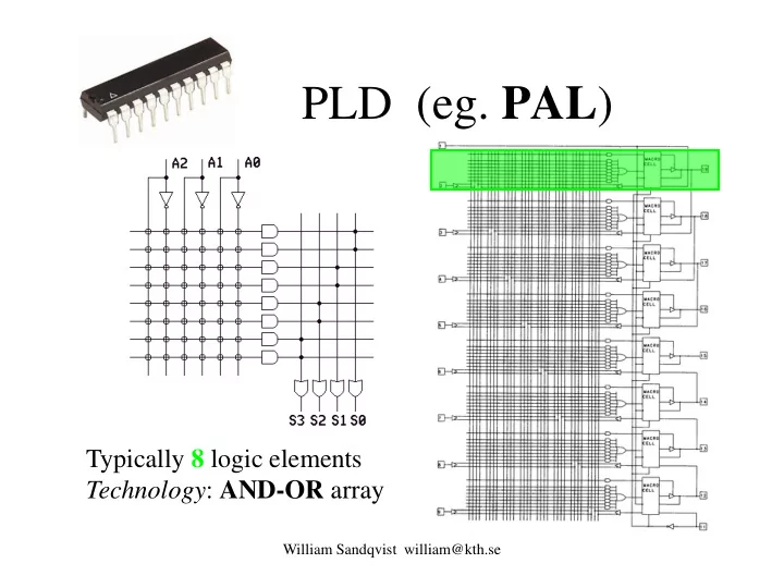
PLD (eg. PAL ) Typically 8 logic elements Technology : AND-OR array - - PowerPoint PPT Presentation
PLD (eg. PAL ) Typically 8 logic elements Technology : AND-OR array William Sandqvist william@kth.se CPLD (eg. MAX) Typically 64 Macrocells Technology : AND-OR array (larger MAX circuits uses MUX-tree technique) William Sandqvist
William Sandqvist william@kth.se
William Sandqvist william@kth.se
William Sandqvist william@kth.se
VA VB VC VQ VDD VSS
William Sandqvist william@kth.se
William Sandqvist william@kth.se
William Sandqvist william@kth.se
William Sandqvist william@kth.se
William Sandqvist william@kth.se
William Sandqvist william@kth.se
William Sandqvist william@kth.se
1 1 1
William Sandqvist william@kth.se
William Sandqvist william@kth.se
x0 0 1
0 0
William Sandqvist william@kth.se
William Sandqvist william@kth.se
x0 x1 1 0 1
1 ⋅
1 1 1
William Sandqvist william@kth.se
x0 x1 1 0 1
1 +
1 1 1 1 1 1 1
William Sandqvist william@kth.se
x0 x1 1 0 1
1 ⊕
1 1 1
William Sandqvist william@kth.se
William Sandqvist william@kth.se
1 1 1 1 x y z 00 01 11 10 1
x y f
Choose any of the inputs as address inputs ... ... And minimize / implement function that occur? For each input. Draw new Karnaugh diagrams if necessary.
11 10 01 00 An (n + 1)-input function could be implemented with a MUX having n select-inputs!
z z 1
William Sandqvist william@kth.se
William Sandqvist william@kth.se
1 1 1
n n n
William Sandqvist william@kth.se
1 1 1 1
n n n
2 10 1 2 11 1 1 1
n n n
William Sandqvist william@kth.se
Right hand side:
if x0=1 so is the right term zero. Then the f is equal to the left term. if x0=0 so is the left term zero. Then the f is equal to the right term.
Left hand side:
if x0=1 so is f equal to f(xn,...,x1,1) (= left term on right side) if x0=0 so is f equal to f(xn,...,x1,0) (= right term on right side)
LHS=RHS
1 1 1
n n n
William Sandqvist william@kth.se 1
z
1 1
y
1 1 1 1
x
111 1 011 0 101 0 001 1 110 0 010 1 100 1 000 0 Address Address pins Value 1 1 1 1 yz x 00 01 11 10 1
f f
William Sandqvist william@kth.se
x1 x2 f Two-input LUT
Programmable cells
1 1 1
A LUT with n inputs can realize all combinational functions with n inputs
William Sandqvist william@kth.se
x1 x2 f Two-input LUT
1 1 1
1 2
William Sandqvist william@kth.se
LUT D Q CLK A B C D M RESET
S 1
LUT A B C D f
MSB LSB
6996 1 2 3
William Sandqvist william@kth.se
Bit # 15 Bit # 0 Bit # 1
6996 1 2 3
William Sandqvist william@kth.se
1 2 3 6996
William Sandqvist william@kth.se
William Sandqvist william@kth.se
en a
1
a y y
1
y
2
y
3
1 1 1 1 1 1 1 1 1 1 1 1
a1 en
y3 y2 y1 y0
2-to-4 decoder
William Sandqvist william@kth.se
s1s0 y3 y2 y1 y0
I0
f s
1
s y y
1
y
2
y
3
1 1 1 1 1 1 1 1 1 1 1 1
William Sandqvist william@kth.se
0/1 0/1 ... 0/1 0/1 0/1 ... 0/1 . . . 0/1 0/1 ... 0/1
a0 a1 ... am
Sel0 Sel1 . . . Sel2m
En dn-1 dn-2 ... d0
Threestate buffers Decoder Programable bits
William Sandqvist william@kth.se
2
n
inputs w w
2
n 1
–
y y
n 1 –
n
16:4
William Sandqvist william@kth.se
y0 y1 y2 y3 f a1 a0 1
1
1 1
1 1 1 1 1
William Sandqvist william@kth.se
William Sandqvist william@kth.se
7421/BCD
William Sandqvist william@kth.se
William Sandqvist william@kth.se
William Sandqvist william@kth.se
William Sandqvist william@kth.se
William Sandqvist william@kth.se
Wind direction indicator usually use Gray code to provide safe decoding. Wind direction Wind speed
William Sandqvist william@kth.se
William Sandqvist william@kth.se
William Sandqvist william@kth.se
N=4
1000 1010 1001 1101 1111 1011 1100 0000 0011 0001 0111 0101 0010 0110 0100 0110
William Sandqvist william@kth.se
According to legend, three monks move 64 golden discs, of different sizes, from one bar to another. The discs should be moved one by one, and they must always be placed so that a smaller disc ports on a larger disc. When the monks are done with their work the earth will go under - it will take 264 moves, so the whole thing will probably take a while ...
William Sandqvist william@kth.se William Sandqvist william@kth.se
William Sandqvist william@kth.se
Gray/Bin
William Sandqvist william@kth.se
William Sandqvist william@kth.se
William Sandqvist william@kth.se
Cin A B S Cout
entity fulladder is port( A,B,Cin : IN std_logic; S,Cout : OUT std_logic); end fulladder;
William Sandqvist william@kth.se
Cin A B S Cout
architecture behave of fulladder is begin S <= A xor B xor Cin; Cout <= (A and B) or (A and Cin) or (B and Cin); end behave;
William Sandqvist william@kth.se
William Sandqvist william@kth.se
William Sandqvist william@kth.se
Generics Ports Entity Architecture Architecture Architecture (structural) Process Sequential Statements Concurrent Statements Package Concurrent Statements
William Sandqvist william@kth.se
Input Output Behavioral Entity
responses to signals and inputs
The inside is not visible from the outside – The entity's behavior is defined by the black box functionality
William Sandqvist william@kth.se
ENTITY xor_gate IS PORT( x, y: IN bit; q: OUT bit); END xor_gate;
William Sandqvist william@kth.se
and the outside world.
– The name of the port – The direction of the port – The port's datatype
ENTITY test IS PORT( name : direction data_type); END test;
William Sandqvist william@kth.se
William Sandqvist william@kth.se
a time.
behavior.
ARCHITECTURE behavior OF xor_gate IS BEGIN q <= a xor b after 5 ns; END behavior;
William Sandqvist william@kth.se
LIBRARY ieee; USE ieee.std_logic_1164.ALL; ENTITY Multiplexer_41 IS PORT(ce_n : IN std_logic; -- Chip En(active low) data_in : IN std_logic_vector(3 DOWNTO 0); sel : IN std_logic_vector(1 DOWNTO 0); data_out : OUT std_logic); -- TriState Output END ENTITY Multiplexer_41; sel(1) sel(0) data_out 11 10 01 00 data_in(3) data_in(2) data_in(1) data_in(0) ce_n
William Sandqvist william@kth.se
ARCHITECTURE RTL OF Multiplexer_41 IS BEGIN PROCESS(ce_n, data_in, sel) BEGIN IF ce_n = '1' THEN data_out <= 'Z'; ELSE CASE sel IS WHEN "00"=> data_out <= data_in(0); WHEN "01"=> data_out <= data_in(1); WHEN "10"=> data_out <= data_in(2); WHEN "11"=> data_out <= data_in(3); WHEN OTHERS => null; END CASE; END IF; END PROCESS; END ARCHITECTURE RTL;
William Sandqvist william@kth.se
William Sandqvist william@kth.se
William Sandqvist william@kth.se
William Sandqvist william@kth.se
William Sandqvist william@kth.se
William Sandqvist william@kth.se
William Sandqvist william@kth.se
process(x,y) begin if (x/=y) then q <= ‘1’; else q <= ‘0’; end if; end process;
William Sandqvist william@kth.se
William Sandqvist william@kth.se
x y q
yi xi t3 t4
William Sandqvist william@kth.se
ARCHITECTURE test OF test_entity COMPONENT and_gate PORT ( in1, in2 : IN BIT;
END COMPONENT; ... more statements ...
in1 in2
William Sandqvist william@kth.se
ARCHITECTURE test OF test_entity COMPONENT and_gate PORT ( in1, in2 : IN BIT;
END COMPONENT; SIGNAL S1, S2, S3 : BIT; BEGIN Gate1 : and_gate PORT MAP (S1,S2,S3); END test;
in1 in2
S1 S2 S3
William Sandqvist william@kth.se
ENTITY adder IS GENERIC(N:integer) PORT(a,b:IN bit_vector(N-1 downto 0); sum:OUT bit_vector(N-1 downto 0)); END adder; ARCHITECTURE structural OF adder IS COMPONENT full_adder PORT(a,b,cin:IN bit;cout,s:OUT bit); END COMPONENT; signal c:bit_vector(N-2 downto 0); BEGIN G0:for i in 1 to N-2 generate U0:full_adder PORT MAP (a(i),b(i),c(i-1),c(i),s(i)); end generate; -- G0 U0:full_adder PORT MAP (a(0),b(0),’0’,c(0),s(0)); UN:full_adder PORT MAP (a(N-1),b(N-1),c(N-2),OPEN,s(N-1); END structural;
William Sandqvist william@kth.se
FA
a1 b1 cin1
FA
a0 b0 cin0 s0 s1
FA
an-1 bn-1 cinn-1 sn-1 cut0 cutn-1
William Sandqvist william@kth.se
– Generating stimuli for simulation – Apply these stimuli to an entity to be tested – Comparing the output values with expected values
William Sandqvist william@kth.se
ENTITY testbench IS END testbench; ARCHITECTURE xor_stimuli_1 of testbench IS COMPONENT xor_gate PORT(x,y:IN bit; q:OUT bit); END COMPONENT; signal x,y,u1,ut2,ut3:bit; BEGIN x <= not(x) after 10 ns; y <= not(y) after 20 ns; U1:xor_gate PORT MAP (x,y,ut1); U2:xor_gate PORT MAP (x,y,ut2); U3:xor_gate PORT MAP (x,y,ut3); END example;
William Sandqvist william@kth.se
William Sandqvist william@kth.se