platform cylinder
play

Platform Cylinder Courtesy of CMA/Flodyne/Hydradyne Motion Control - PDF document

Platform Cylinder Courtesy of CMA/Flodyne/Hydradyne Motion Control Hydraulic Pneumatic Electrical Mechanical (800) 426-5480 www.cmafh.com Series CXT 12, 16, 20, 25, 32, 40 A highly rigid and highly


  1. Platform Cylinder Courtesy of CMA/Flodyne/Hydradyne ▪ Motion Control ▪ Hydraulic ▪ Pneumatic ▪ Electrical ▪ Mechanical ▪ (800) 426-5480 ▪ www.cmafh.com Series CXT ø 12, ø 16, ø 20, ø 25, ø 32, ø 40 
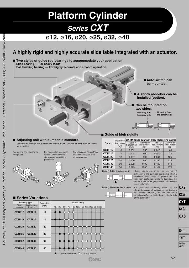
A highly rigid and highly accurate slide table integrated with an actuator. Two styles of guide rod bearings to accommodate your application Slide bearing — For heavy loads Ball bushing bearing — For highly accurate and smooth operation Auto switch can be mounted. A shock absorber can be installed (option). Can be mounted on two sides. Mounting from Mounting from the upper side the bottom side Guide of high rigidity Adjusting bolt with bumper is standard. CXTM (Slide bearing) CXTL (Ball bushing bearing) Maximum (1) Allowable (2) Table (1) Allowable (2) Table Series load mass Performs the function of a cushion and adjusts the stroke 5 mm on each side, or 10 mm displacement static mass displacement static mass (kg) for both sides. (kg) (mm) (kg) (mm) CXT � 12 3 0.002 350 0.015 60 For moving and transferring For moving the receptacle For using as a Pick & Place CXT � 16 7 0.004 500 0.019 70 workpieces. for workpieces used in unit in combination with CXT � 20 12 0.007 900 0.044 125 stamping or press-fitting other actuators. processes. CXT � 25 20 0.030 900 0.180 125 CXT � 32 30 0.032 1100 0.123 140 CXT � 40 50 0.025 1900 0.109 170 Note 1) Table displacement “Table displacement” is the amount of deflection of the guide rod that occurs when a maximum load mass is placed on the maximum stroke table while the table is at the center of the stroke (the amount of looseness is not included). CX2 Note 2) Allowable static mass An “allowable stationary mass” is the allowable amount of stationary mass that can be applied vertically to the workpiece CXW mounting surface of the table while the table is � Series Variations at the stroke end. CXT Bearing type Stroke (mm) Bore size Slide Ball bushing (mm) 15 25 50 75 100 125 150 175 200 250 300 bearing bearing CXSJ CXTM12 CXTL12 12 CXS CXTM16 CXTL16 16 CXTM20 CXTL20 20 D- � CXTM25 CXTL25 25 -X � CXTM32 CXTL32 32 Individual -X � CXTM40 CXTL40 40 ······Standard stroke ······Long stroke 521

  2. Series CXT Model Selection Courtesy of CMA/Flodyne/Hydradyne ▪ Motion Control ▪ Hydraulic ▪ Pneumatic ▪ Electrical ▪ Mechanical ▪ (800) 426-5480 ▪ www.cmafh.com Selection Step Setting Conditions 1. Mounting (Horizontal, Inclined, Vertical) 2. Load mass W (kg) 3. Operating pressure P (MPa) P ≤ 0.7 MPa 4. Speed V (mm/s) V ≤ 500 mm/s Guideline for Selection of Bearing Type Bearing type Required conditions • Impact load and vibration load are added. Slide bearing • Change in load is large. • Long life span is required. Selection of bearing type • High accuracy (Little rattle is allowed.) Ball bushing bearing • Smooth operation Load mass [W] Moment [m n ] Σ α n = —————————————— + ——————————— Maximum load mass [Wmax] Allowable moment [Mn] Provisional selection of cylinder bore size Load mass [ W ] are as follows in compliance to the mounting way. Horizontal mounting : W Inclined mounting : Wcos θ ( θ : Angle of inclination, refer to the figure below.) Vertical mounting: 0 (None) The moment load rate must be calculated in accordance with the above NO formula for all types, M1 to M3 . Confirmation of sum As for Wmax and Mn , refer to the maximum load mass and allowable of load ratio to the guide unit moment table in the next section. Σ α n ≤ 1 The moment for the inclined mounting must be calculated taking the moment caused by the load into consideration. Note) Make sure that the distance between the guide shaft center to the center of gravity of the load does not exceed the distance GP between YES the guide shafts given in the table below. If the distance must be exceeded due to unavoidable circumstances, decrease the load rate that is applied to the guide as indicated below in order to determine the distance. Calculation of resistance force f 1 Σ α n ≤ ———— (Provided that L > GP ) 2 (L/GP) Calculation of theoretical output F L W (mm) Refer to “Theoretical 12 16 20 25 32 40 Bore size Output” on page 525. Distance between guide rods GP 50 65 80 90 110 130 GP β > 0.5 Calculation of load ratio β to the theoretical output of cylinder Horizontal mounting: f = µ x W β = f / F Inclined mounting: f = µ x Wcos θ + Wsin θ W (Refer to the figure on the right.) Vertical mounting: f = W µ = 0.3 (Slide bearing) β ≤ 0.5 µ = 0.1 (Ball bushing bearing) θ θ NO Confirmation of adjusting bolt capacity Determine the movable mass W A which can be operated W ≤ W A only by adjusting bolts. YES Model selected Model selected Without shock absorber With shock absorber 522

  3. Series CXT Courtesy of CMA/Flodyne/Hydradyne ▪ Motion Control ▪ Hydraulic ▪ Pneumatic ▪ Electrical ▪ Mechanical ▪ (800) 426-5480 ▪ www.cmafh.com Non-rotating Accuracy of Slide Block CXTM CXTL θ p θ r θ y Bore size (Slide bearing) (Ball bushing bearing) (mm) θ p (= θ y) θ r θ p (= θ y) θ r 12 ± 0.09 ° ± 0.12 ° ± 0.05 ° ± 0.05 ° 16 ± 0.08 ° ± 0.10 ° ± 0.05 ° ± 0.04 ° Pitching direction Rolling direction Yawing direction 20 ± 0.07 ° ± 0.08 ° ± 0.04 ° ± 0.03 ° 25 ± 0.07 ° ± 0.07 ° ± 0.04 ° ± 0.03 ° 32 ± 0.08 ° ± 0.07 ° ± 0.04 ° ± 0.03 ° 40 ± 0.06 ° ± 0.06 ° ± 0.03 ° ± 0.03 ° Maximum Load Mass and Allowable Moment Allowable moment (N · m) Bore size Maximum load mass Bearing (mm) Wmax (kg) M1 (= M3) M2 M3 Slide bearing 1.25 1.68 M1 M2 12 3 Ball bushing bearing 0.53 0.70 Slide bearing 3.34 4.25 16 7 Ball bushing bearing 1.53 2.11 l l Slide bearing 11.4 17.1 20 12 Ball bushing bearing 5.60 7.28 Note) For the purpose of calculating the moment, the length of the arm is the Slide bearing 11.4 19.3 distance that is measured from the guide shaft center (“ � ” mark). 25 20 Ball bushing bearing 5.60 8.19 Dimension l from the guide shaft center to the top surface of the table is indicated below. Slide bearing 19.8 23.3 32 30 Ball bushing bearing 10.1 14.8 (mm) Slide bearing 37.3 46.2 Bore size 12 16 20 25 32 40 40 50 Ball bushing bearing 21.3 27.5 l dimension 19.5 24 28 31 39.5 47.5 Allowable Load Only by Adjusting Bolt If only the adjusting bolt is used for stopping the load, make sure that the load mass and the speed will be below the curve in the 50 graph on the right, taking into consideration the durability of the 45 rubber bumper that is attached to the end of the adjusting bolt and 40 the vibration and noise that are created when stopping (provided that the maximum load mass is not exceeded). 35 Load mass (kg) 30 In conditions in which the load mass and the speed will be above 25 the curve, use a shock absorber (provided that the maximum load mass is not exceeded). 20 15 Caution 10 In the case of the ball bushing type, the service life could be 5 drastically shortened if shocks or excessive moments are applied. Therefore, even if the conditions given above are not 0 100 200 300 400 500 exceeded, the use of a shock absorber is recommended. CX2 Speed (mm/s) CXW Static Movable Mass when Stopped CXT When Series CXT cylinder is used for moving the workpiece receptacle, such as in a stamping or press-fitting process, a vertical load will be applied to the top surface of the stopped slide block Allowable Static Mass CXSJ (kg) (refer to the figure on the right). In this case, the allowable mass is Bore size CXTM CXTL greater than the maximum load mass, as given in the table on the (mm) (Slide bearing) (Ball bushing bearing) CXS right. 12 350 60 Caution 16 500 70 20 900 125 1. Make sure that the slide block is stopped at the stroke end. D- � 2. Match the center of the mass to be applied with the center 25 900 125 of the slide block. The direction of the mass must be 32 1100 140 vertically downward in relation to the surface on which the -X � 40 1900 170 workpiece is mounted, as shown in the figure on the right. 3. Do not apply a load that involves shocks such as those Individual caused by pounding (particularly with the ball bushing -X � style). 4. If this mass is applied, the deflection of the guide shaft will also have a large value. 523

Download Presentation
Download Policy: The content available on the website is offered to you 'AS IS' for your personal information and use only. It cannot be commercialized, licensed, or distributed on other websites without prior consent from the author. To download a presentation, simply click this link. If you encounter any difficulties during the download process, it's possible that the publisher has removed the file from their server.

Recommend


More recommend