
SLIDE 1
Page 1
(1)
Pipelining: Its Natural!
- Laundry Example
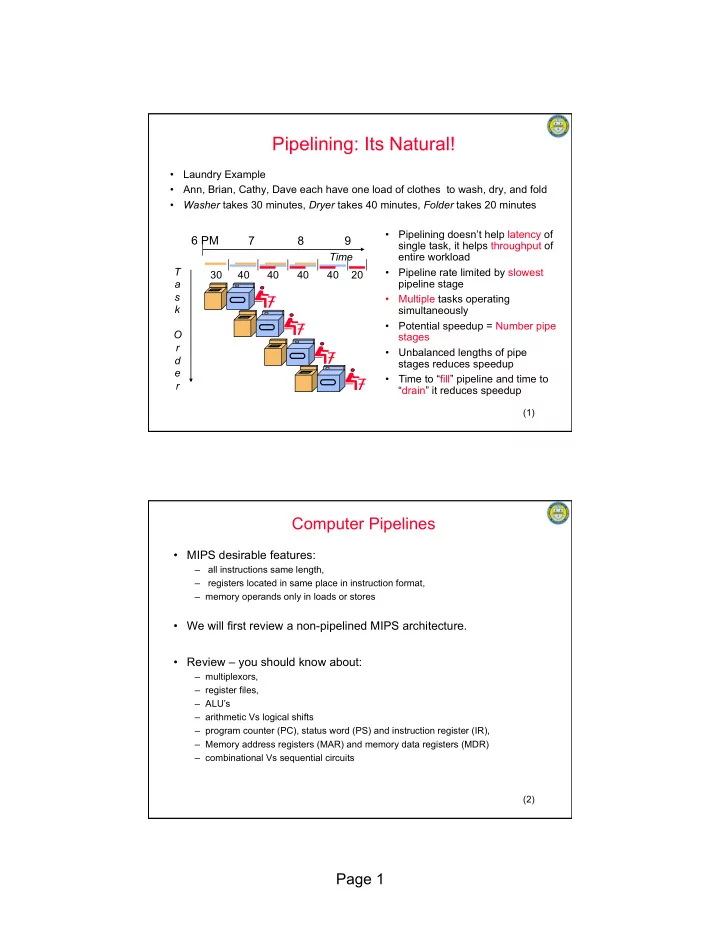
- Ann, Brian, Cathy, Dave each have one load of clothes to wash, dry, and fold
- Washer takes 30 minutes, Dryer takes 40 minutes, Folder takes 20 minutes
6 PM 7 8 9
T a s k O r d e r Time 30 40 40 40 40 20
- Pipelining doesn’t help latency of
single task, it helps throughput of entire workload
- Pipeline rate limited by slowest
pipeline stage
- Multiple tasks operating
simultaneously
- Potential speedup = Number pipe
stages
- Unbalanced lengths of pipe
stages reduces speedup
- Time to “fill” pipeline and time to
“drain” it reduces speedup
(2)
Computer Pipelines
- MIPS desirable features:
– all instructions same length, – registers located in same place in instruction format, – memory operands only in loads or stores
- We will first review a non-pipelined MIPS architecture.
- Review – you should know about:
– multiplexors, – register files, – ALU’s – arithmetic Vs logical shifts – program counter (PC), status word (PS) and instruction register (IR), – Memory address registers (MAR) and memory data registers (MDR) – combinational Vs sequential circuits