
SLIDE 1
6a.1
EE 457 Unit 6a
Basic Pipelining Techniques
6a.2
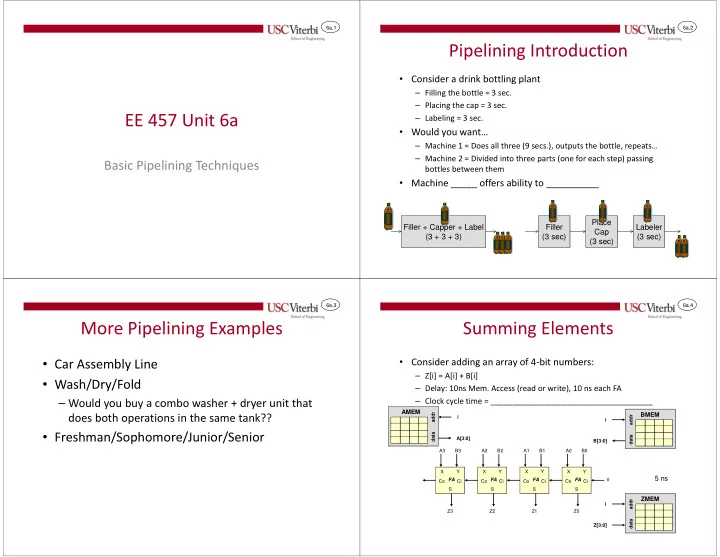
Pipelining Introduction
- Consider a drink bottling plant
– Filling the bottle = 3 sec. – Placing the cap = 3 sec. – Labeling = 3 sec.
- Would you want…
– Machine 1 = Does all three (9 secs.), outputs the bottle, repeats… – Machine 2 = Divided into three parts (one for each step) passing bottles between them
- Machine _____ offers ability to __________
Filler + Capper + Label (3 + 3 + 3) Filler (3 sec) Place Cap (3 sec) Labeler (3 sec)
6a.3
More Pipelining Examples
- Car Assembly Line
- Wash/Dry/Fold
– Would you buy a combo washer + dryer unit that does both operations in the same tank??
- Freshman/Sophomore/Junior/Senior
6a.4
Summing Elements
- Consider adding an array of 4-bit numbers:
– Z[i] = A[i] + B[i] – Delay: 10ns Mem. Access (read or write), 10 ns each FA – Clock cycle time = _____________________________________
X Y S Ci Co FA
5 ns
X Y S Ci Co FA X Y S Ci Co FA X Y S Ci Co FA
BMEM
addr data
AMEM
addr data i i A[3:0] B[3:0] A0 B0 A1 B1 A2 B2 A3 B3
ZMEM
addr data i Z[3:0] Z0 Z1 Z2 Z3