SLIDE 1 Photorealism
Steve Ash, Rhodes College 2006
SLIDE 2
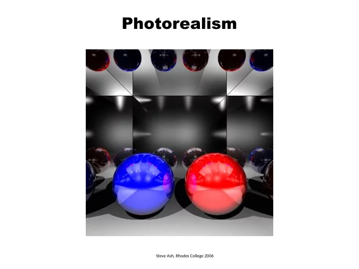
Photorealism
The goal is to model the interaction between light source and surface materials ambient light diffuse reflection specular reflection transparency
SLIDE 3
Photorealism
The goal is to model the interaction between light source and surface materials ambient light diffuse reflection scattered light illuminating the object (the light source has no direction) point -light illuminating the object light is reflected equally in all directions
SLIDE 4
Photorealism
The goal is to model the interaction between light source and surface materials specular reflection transparent interaction between light and a highly reflective (shiny) surface interaction between light and a highly transparent surface
SLIDE 5 Algorithm
For each pixel P in the canvas: shoot a ray V from the eye E to P find intersection point Q with object find color of object at Q which depends on: * object material and light source properties set pixel P to computed color
(x,y,0) (ex,ey,ez)
L V N
(lx,ly,lz)
SLIDE 6
Light and Materials
Light sources will be modeled by their intensity I = (R, G, B) and position P = (X, Y, Z) no position for ambient light, just intensity Material properties of objects will be modeled by O = (R, G, B) coeff. of reflection e.g. high R coefficient will imply material that appears more Red The color, I, observed on the object will be the sum total of the interactions of all light sources and the material properties of the object I = Ambient + Diffuse + Specular + Transparent
SLIDE 7
Light and Materials
Point light sources modeled by their intensity Ip = (R, G, B) and position P = (X, Y, Z) no position for ambient light, just intensity Ia Intrinsic color of the object specified by O = (R, G, B) Material properties of objects modeled by various coefficients of reflection ka – ambient coefficient kd – diffuse coefficient ks – specular coefficient n – specular highlight kt – transparency coefficient η – index of refraction The intensity observed on the object will be the sum total of the interactions of all light sources and the color and material properties of the object I = Ambient + Diffuse + Specular + Transparent
SLIDE 8
Ambient Component
To model the ambient intensity determine how much ambient light is reflected Ambient = ka IaOa This is done for each color channel λ = (R, G, B) Ambientλ = ka IaλOλ AmbientR = ka IaROR AmbientG = ka IaGOG AmbientB = ka IaBOB
SLIDE 9
Diffuse Component
Diffuse describes matte surfaces light is reflected equally in all directions amount of reflected light depends on amount of surface area hit independent of viewer pos smaller area hit, so more intensity per unit area, but viewer sees less larger area hit, so viewer sees more, but less intensity per unit area
SLIDE 10
Diffuse Component
Diffuse describes matte surfaces light is reflected equally in all directions amount of reflected light depends on amount of surface area hit smaller area hit, so more intensity per unit area, but viewer sees less larger area hit, so viewer sees more but less intensity per unit area The effect cancels out – see more, but less intense, or see less but more intense diffuse component proportional to cos θ between light and surface normal N L θ Diffuse λ = kd IpλOλ cos θ = kd IpλOλ(N•L) Itotal = A1 IΔ1 = A2 IΔ2 Itotal Itotal A1 A2
SLIDE 11
Specular Component
The specular highlight is a region of high intensity moves along the surface depending on viewer position highly concentrated – falls off quickly with viewing angle
SLIDE 12
Specular Component
The specular highlight is a region of high intensity moves along the surface depending on viewer position highly concentrated – falls off quickly with viewing angle Phong model for specular reflection specular highlight depends on angle between reflect ray R and the gaze V N L α R V θ θ N L α R V θ θ same ray in each case left viewer will see less reflection right viewer will see less reflection since reflected ray diverges more since closer to reflected ray
SLIDE 13
Specular Component
The specular highlight is a region of high intensity moves along the surface depending on viewer position highly concentrated – falls off quickly with viewing angle Phong model for specular reflection specular highlight depends on angle between reflect ray R and the gaze V N L R V N L R V highest perceived intensity when R = V varies with viewer position
SLIDE 14
Specular Component
The specular highlight is a region of high intensity moves along the surface depending on viewer position highly concentrated – falls off quickly with viewing angle Phong model for specular reflection specular highlight depends on angle between reflect ray R and the gaze V N L α R V θ θ Specular λ = ks IpλOλ cosn α = ks IpλOλ(R•V)n n – specular reflection exponent high n, more focused (smaller) highlight
SLIDE 15
Specular Component
Calculating R, assuming L, N unit N L R θ θ
SLIDE 16
Specular Component
Calculating R, assuming L, N unit N L R θ θ N' L R θ θ S S Shrink N to level L, N', R N' = N * ( |L| * cos θ ) = N * cos θ
SLIDE 17
Specular Component
Calculating R, assuming L, N unit We have R = N’ + S S = N’ – L N L R θ θ N' L R θ θ S S Shrink N to level L, N', R N' = N * ( |L| * cos θ ) = N * cos θ
SLIDE 18
Specular Component
Calculating R, assuming L, N unit We have R = N’ + S S = N’ – L Therefore R = N’ + S = N' + (N' - L) = 2N' – L = 2N cos θ – L R = 2N(N•L) – L N L R θ θ N' L R θ θ S S Shrink N to level L, N', R N' = N * ( |L| * cos θ ) = N * cos θ
SLIDE 19
Specular Component
Calculating R, assuming L, N unit We have R = N’ + S S = N’ – L Therefore R = N’ + S = N' + (N' - L) = 2N' – L = 2N cos θ – L R = 2N(N•L) – L Now can compute Specularλ = ks IpλOλ(R•V)n N L R θ θ N' L R θ θ S S Shrink N to level L, N', R N' = N * ( |L| * cos θ ) = N * cos θ
SLIDE 20 Summary
The color, I, observed on the object will be the sum total of the interactions of all light sources and the material properties of the object I = Ambient + Diffuse + Specular + Transparent Iλ = ka IaλOλ + kd IpλOλ(N•L) + ks IpλOλ(R•V)n + Transparent Ia – the intensity of the ambient light Ip – the intensity of the point light source O – the intrinsic color of the object ka, kd, ks – ambient, diffuse, specular coefficients this is done for each color channel λ = (R, G, B)
SLIDE 21 Algorithm
For each pixel P in the canvas: shoot a ray V from the eye E to P find intersection point Q with object find surface normal N at intersection point Q find the directions (unit vectors): L (Q to light) R (reflected ray L) V (Q to eye) Itotal = Ambient + Diffuse + Specular set pixel P to Itotal
(x,y,0) (ex,ey,ez)
X L V N R
(lx,ly,lz)
SLIDE 22
Ray-Sphere Intersection
Sphere equation (x – cx)2 + (y – cy) 2 + (z – cz) 2 - R2 = 0 Ray equation p = source + t*direction px = sx + t*dx py = sy + t*dy pz = sz + t*dz Common point (px – cx) 2 + (py – cy) 2 + (pz – cz) 2 - R2 = 0 (sx + t*dx – cx) 2 + (sy + t*dy – cy) 2 + (sz + t*dz – cz) 2 - R2 = 0 t = ? could have 0, 1, or 2 solutions which one should we pick
SLIDE 23
Sphere Surface Normal
C P N N is of unit length and has the same direction as CP ray
SLIDE 24 Scene Specification
camera { location <0, 0, 80> screen_size 60 density 300 } light_ambient { rgb <0.2, 0.1, 0.1> } light_source { <-100, 125, 150>, rgb <1.0, 1.0, 1.0> } sphere { <10, 0, -20>, 35 color { rgb <0.0, 1.0, 0.0> } finish { ambient 0.2 diffuse 0.4 specular 0.8 phong_size 90 transparent 0.9 index 1.33 } }
(0,0,80) (-100,125,150) (10,0,-20) 60 60 300 -- #rays per row/column
image source: http://en.wikipedia.org/wiki/File:Ray_trace_diagram.svg
SLIDE 25 Scene Specification
camera { camera { location <0, 0, 80> location <0, 0, 80> screen_size 60 screen_size 60 density 300 density 40 } }
window is 60x60 but 300 rays so we need 300 x 300 Canvas windows is 60x60 but 40 rays so we need 40 x 40 Canvas ∆w = fit 40 into 60 ∆w = fit 300 into 60
+30
+30
+30 +30 window (-30,+30) is (0,0) in canvas window (+30,-30) is (300,300) in canvas window (-30,+30) is (00) in canvas window (+30,-30) is (40,40) in canvas
SLIDE 26 Single Object Multiple Light Sources
For each pixel P in the image: shoot a ray from the eye E to P find intersection point Q with object find surface normal N at intersection point Q for each light source S: find the directions: L (Q to S) R (reflected ray L) V (Q to eye) compute intensity for S: IS = Diffuse + Specular Itotal = Ambient + Sum IS (all visible light sources) set pixel (x, y) to Itotal
X
SLIDE 27 Multiple Objects and Shadows
For each pixel P in the image: shoot a ray from the eye E to P find intersection point Q with closest object find surface normal N at intersection point Q for each light source S visible from Q: find the directions: L (Q to S) R (reflected ray L) V (Q to eye) compute intensity for S: IS = Diffuse + Specular Itotal = Ambient + Sum IS (all visible light sources) set pixel (x, y) to Itotal
X
and not blocked by other object
SLIDE 28 Multiple Lights, Objects and Shadows
Shadows and multiple lights are handled by checking whether each light source illuminates the hit point directly I = Ambient + Diffuse + Specular Iλ = ksIaλOλ + ∑Si [ksIpiλOλ(N•L) + ksIpiλOλ(R•V)n ] Si = 1 if point light Ipi illuminates intersection point 0 if point light Ipi does not illuminate:
- another object blocks the light path
- this object blocks the light path N • L < 0