Phosphates for Lithium-ion ion Intro roduct ction Batteri ries: - - PDF document

phosphates for lithium ion ion
SMART_READER_LITE
LIVE PREVIEW

Phosphates for Lithium-ion ion Intro roduct ction Batteri ries: - - PDF document

2/29/2008 Overvi view of Prese senta tati tion Phosphates for Lithium-ion ion Intro roduct ction Batteri ries: : Materials ials, , Synthesis is and Carbotherm rmal Reduct ction Future re Opport rtuniti ties Why y Phosphates?


slide-1
SLIDE 1

2/29/2008 1

1

Valenc ence e Techno hnology

  • gy Inc.

Jerry y Barke ker Consu sulta ltants ts Specialists cialists in Electr troch chemica ical and Solid-Sta tate te Chemistr istry y www.je .jerryb ybarker.c .co.u .uk

Phosphates for Lithium-ion ion Batteri ries: : Materials ials, , Synthesis is and Future re Opport rtuniti ties

2

Overvi view of Prese senta tati tion

Intro roduct ction Carbotherm rmal Reduct ction Why y Phosphates? s? Olivi vines Nasico cons Fluoro rophosp sphates, s, LiVPO4F and Na3V2(PO (PO4)2F3 New Opport rtunities, s, New Cell Struct cture res Conclusi sions

3

Introduct ctio ion

  • Valence Technology has been working on Phosphate Active

Materials since the early 1990’s.

  • Has built up a large portfolio of lithium and sodium active

materials – phosphates, condensed phosphates, fluorophosphates and other polyanions (100+ + patents on active materials)

  • Valence needed a cost effective and scalable process for making

these active materials at a commercial scale. Developed the Carbothermal Reduction (CTR) Method.

  • Today, Valence makes active materials using the CTR approach

– up to Metric Tonne/day scale.

4

Carboth thermal l Reducti tion

  • The Carboth

thermal l Reductio ction (CTR) R) method utilizes izes a high surfa face ce area carbon as a selective ctive reducing cing agent

  • 2C + O2  2 CO = i

increase se in volume and therefo fore entropy.

  • y. Carbon is

uniqu ique in that CO free energy y of formatio tion becomes s increasing ingly ly negative tive as the temperatu ture increase ses s – i.e. more stable le at high temperatu tures.

  • s. Impli

lica catio tions: s: Carbon can reduce ce any oxide provide vided a high enough temperature can be reach ched. . Example: le: Na extractio ction: Na Na2CO CO3 (liquid) + 2 C (solid) → 2 Na (vapor) + 3 CO (gas)

  • By design

ign, , the CTR techniqu ique leave ves behind ind an embedded conductive tive netwo twork. k.

  • Carbon monoxide

xide formed during ing the synth thesis sis both promote tes s furth ther reduction and deposits carbon “nanoparticles”

  • Net resu

sult: lt: precu curso sor carbon is finely ly distr tribu ibute ted throughout t and on surfa face of final l product. t.

5

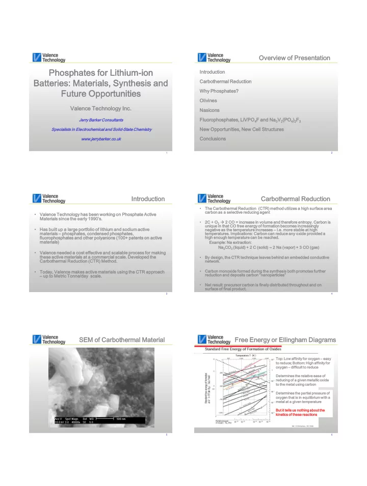
SEM M of Carbothermal l Material l

6

Free Energy y or Ellin ingham Diagrams

Top: Low affinit inity for oxygen gen – easy to reduc uce; Bottom

  • m: High

h affinit inity for

  • xygen

en – diffic icult ult to reduc uce Determ rmin ines es the relat ativ ive e ease e of reduc ucing ing of a given en metallic llic oxide de to the metal l using ng carbon bon Determ rmin ines es the partial ial pressure ure of

  • xygen

en that at is in equilibrium ilibrium with h a metal al at a given en temperat peratur ure But it tells ls us nothing hing about ut the kinet netic ics of these e reactio ions ns

slide-2
SLIDE 2

2/29/2008 2

7

Iron Blast Furnace ce

Reaction Mechanisms: 3 Fe2O3 + CO  2 Fe3O4 + CO2 Fe Fe2+/3+ Fe Fe3O4 + CO  3 3 FeO FeO + CO2 Fe Fe2+

2+

FeO FeO + CO  Fe + CO2 Fe Fe0 Intermediate Oxidation States: Fe Fe3+

3+  Fe

Fe2+

2+

Mn Mn3+

3+  Mn

Mn2+

2+

V5+

5+  V3+ 3+

Mo Mo6+

6+  Mo

Mo4+

4+ etc.

Metal Oxide Metal Oxide

Lithiated Metal Phosphate Before reaction: Mixture of carbon, metal

  • xide, phosphate and lithium salts

The CO produced promotes reduction while residual carbon remains as carbon “nanoparticles” Lithium Metal Phosphate starts to form as the oxide is reduced Net result: as the product is formed, precursor carbon is distributed throughout and on surface of final product

lithium salt carbon

CTR: R: Schematic tic Represe senta tatio tion

9

Valenc ence e Studi died ed Phosph sphat ates es

Material Nominal Voltage vs. Li Specific c Capacity y mAh/g Inventor US Patent# Comments LiFePO4 3.45 140-160

  • J. Goodenough

US 5910382 and others Olivine LiFe1-xMxPO4 3.45 140-160 J.Barker et al US 6884544 and others M = Mg, Ca, Zn Li3V2(PO4)3 3.6-4.7 197 J.Barker et al US 5871866 and others Nasicon LiVPO4F 4.2 155 J.Barker et al US 6387568 and others Triclinic LiVPO4.OH 4.1 158 J.Barker et al US 6777132 and others Triclinic LiVP2O7 4.1 116

  • Diphosphate

Li2MPO4F 4.7 143 J.Barker et al US 6964827 and others M = Co, Ni etc. Na2MPO4F 4.7 122 J.Barker et al US 6872492 and others M = Co, Ni etc. Li4V2(SiO4)(PO4)2 3.6-4.7 260 J.Barker et al US 6136472 and others Silicophosphate Li3V1.5Al0.5(PO4)3 3.6-4.7 203 J.Barker et al US 5871866 and others Nasicon β-LiVOPO4 4.0 159 J.Barker et al US 6645452 (CTR) Prepared by CTR NaVPO4F 3.7 143 J.Barker et al US 6872492 and others Sodium Ion Na3V2(PO4)2F3 3.7 192 J.Barker et al US 6872492 and others Sodium Ion Novel Phase A 3.8

  • ca. 150

J.Barker et al Pending Application Pending Novel Phase B 3.9

  • ca. 140

J.Barker et al Pending Application Pending Novel Phase C 3.5

  • ca. 145

J.Barker et al Pending Application Pending 10

Phosphate te Chemis istr try y

1.5 2.0 2.5 3.0 3.5 4.0 4.5 5.0 50 100 150 200 LVP LiVPO4.OH LiCoPO4 Na3V2(PO4)2F3 LiFe1-xMgxPO4 Li2CoPO4F LiVPO4F LiVP2O7 LiVOPO4 Li3Ti2(PO4)3 Li3V2(PO4)3 Phase A

Material Specific Capacity [mAh/g] Electrode Potential [V vs Li] 11

Phosphate Chemi mist stry y (cont..)

1.5 2.0 2.5 3.0 3.5 4.0 4.5 5.0 50 100 150 200 Na3V2(PO4)2F3 LiFe1-xMgxPO4 LiVPO4F Li3V2(PO4)3

Material Specific Capacity [mAh/g] Electrode Potential [V vs Li] 12

Phosphate Safety y

100 200 300 400 Exotherm (J/g) Temperature (C) LNO 893 J/g LCO 570 LMO 335 LFP 124 J/g

200 400 600 800 1000 LFP LVPF LVP LCP LMO LCO LNO Heat Flow (J/gr)

slide-3
SLIDE 3

2/29/2008 3

13

Li//γ-LiV iV2O5

0.5 1.0 1.5 2.0 2.5 3.0 3.5 4.0 4.5 25 50 75 100 125 150 0.1 0.2 0.3 0.4 0.5 0.6 0.7 0.8 0.9 1.0 Cathode Specific Capacity [mAh/g] Electrode Potential [V vs. Li/Li

+]

x in LixV2O5

  • 500
  • 400
  • 300
  • 200
  • 100

100 200 300 400 500 1.0 1.5 2.0 2.5 3.0 3.5 4.0 Insertion Extraction Electrode Potential [V vs. Li/Li

+]

Differential Capacity, dQ/dV [C/V] 14

Cycl cling ng of Graphi hite/ e//γ-Li LiV2O5 Protot

  • types

ypes

25 50 75 100 125 150 100 200 300 400 500 600

Cycle # Specific Discharge Capacity (mAhr/g)

23C 60C

15

LiFe1-xMg MgxPO PO4

4

3-Dim imens ensional ional Framew ework

  • rk

Struc ructure ure Framew ework rk compris prises es PO4 tetrah rahedra edra and MO6 octahed ahedra ra Fe and Mg occupy upy the same e crystallograph allographic ic posit itio ion Cont ntrolled rolled morphology hology and partic icle le size e give e rise to fast electro rode de kinet netic ics 150 150-170 70 mAh/g g @ 3.45 5 V vs. Li Metri ric Tonne produc uctio ion

16

Li//L /LiF iFe1-xMg MgxPO PO4

1.0 1.5 2.0 2.5 3.0 3.5 4.0 4.5 20 40 60 80 100 120 140 160 Cathode Specific Capacity [mAh/g] Electrode Potential [V vs. Li]

  • 800
  • 600
  • 400
  • 200

200 400 600 800 2.6 2.8 3.0 3.2 3.4 3.6 3.8 4.0 Electrode Potential [V vs Li] Differential Capacity, dQ/dV [C/V] 17

LiFeP ePO4: : ex ex-si situ u XRD study y of CTR

1000 2000 3000 10 20 30 40 50 60 70

Pre-mix 900 800 700 600 500 400 300

2 Theta. Intensity (A.U.)

LiH2PO PO4 + + ½ ½ Fe Fe2O3 + + ½ ½ C C  LiFePO4 + H2O + ½ CO

18

LiFeP ePO4: : ex ex-si situ XRD study y of CTR

Filename Temp(oC) LiH2PO4 % Fe2O3 % Li3Fe2(PO4)3 % LiFePO4 % Li4P2O7 % LiFeP2O7 % FePO4 % Fe2P2O7 % S3245 300 2.92 76.15 0.40 0.38 0.74 18.59 S3245_1 _1 400 43.74 3.06 1.24 51.959 S3245_2 _2 500 30.54 34.62 4.92 29.92 S3245_3 _3 600 3.32 1.50 91.65 0.84 0.46 2.24 S3245_4 _4 700 0.18 0.96 97.84 0.33 0.33 0.36 S3245_5 _5 800 1.16 96.89 0.84 0.32 0.79 S3245_6 _6 900 1.32 96.73 0.73 0.53 0.69

slide-4
SLIDE 4

2/29/2008 4

19

LiFeP ePO4: : ex ex-si situ XRD study y of CTR

20 40 60 80 100 200 400 600 800 1000

Li3Fe2(PO4)3 LiFeP2O7 Fe2O3 LiFePO4

Temperature of Synthesis (

  • C)

% of Conmposition

Message: LiFePO4

4 starts to forms at <400oC under CTR conditions

20

Cycl cling ng of Graphi hite/ e//Li LiFe1-xMg MgxPO PO4

4 18650

50

10 20 30 40 50 60 70 80 90 100 110 100 200 300 400 500 600 700 800 900 1000 1100 Cycle Capacity

21

Li Li3V2(PO4)3

3-Dim imens ensional ional Framew ework

  • rk Struc

ucture ure Framew ework rk compris prises es PO4 tetrah rahedra edra and slight ghtly ly distort

  • rted

ed MO6

  • ctah

ahedra edra Three ee distinc inct crystallograph allographic ic sites es for r Li+ High gh Li ion mobilit lity gives es rise e to fast insert ertion ion kinet etic ics All 3 Li ions extrac ractable able generat rating ing a spec ecif ific ic capac acit ity close e to theore

  • retic

ical al (197 7 mAh/g) g)

22

Li//Li Li3V2(PO4)3

2.0 2.5 3.0 3.5 4.0 4.5 5.0 50 100 150 200 0.5 1.0 1.5 2.0 2.5 3.0 Cathode Specific Capacity [mAh/g] Electrode Potential [V vs. Li] x in Li3-xV2(PO4)3 23

Graphite ite//Li Li3V2(PO4)3

  • 150
  • 100
  • 50

50 100 150 200 250 2.0 2.5 3.0 3.5 4.0 4.5 5.0 Cell Potential [V] Differential Capacity, dQ/dV [C/V] 1 2 3 4 5 50 100 150 200

167 mAh/g 184 mAh/g

Cathode Specific Capacity [mAh/g] Cell Potential [V] 24

Cycli cling Graphite ite//LVP Prototypes

slide-5
SLIDE 5

2/29/2008 5

25

LiVPO4F

Framew ework rk Triclini linic Struc ucture ure relat ated ed to the minerals rals, Ambly lygonit gonite e LiAlPO lPO4F and Tavorit

  • rite

LiFePO ePO4OH OH Struc ructure ure compris prises a 3D fram amew ewor

  • rk built

lt up from PO4 tetrah rahedra edra and MO4F2 octahe ahedra dra Repres present entat atio ion n left is show

  • wn

n along g the e c-ax axis is V locat ated ed in the MO4F2 octahedra ahedra Elec ectroc rochem emis istry ry sugges gests 2 sites es for r the Li ions

26

Refin ined XRD for LiVPO4F

27

Li//L /LiV iVPO4F

  • 300
  • 200
  • 100

100 200 300 3.6 3.8 4.0 4.2 4.4 4.6 Electrode Potential [V vs Li] Differential Capacity, dQ/dV [C/V] 2.0 2.5 3.0 3.5 4.0 4.5 5.0 20 40 60 80 100 120 140 160 Cathode Specific Capacity [mAh/g] Electrode Potential [V vs. Li]

Theoretical Capacity - 155 mAh/g Reversible Specific Capacity!!

28

Li//L /LiV iVPO4F

2.0 2.5 3.0 3.5 4.0 4.5 5.0 20 40 60 80 100 120 140 160 0.1 0.2 0.3 0.4 0.5 0.6 0.7 0.8 0.9 1.0 Cathode Specific Capacity [mAh/g] Electrode Potential [V vs. Li] x in Li1-xVPO4F 29

Graphite ite//LiV iVPO4F

0.5 1.0 1.5 2.0 2.5 3.0 3.5 4.0 4.5 5.0 20 40 60 80 100 120 140 160 Cathode Specific Capacity [mAh/g] Cell Voltage [V]

  • 300
  • 200
  • 100

100 200 300 2.0 2.5 3.0 3.5 4.0 4.5 5.0 Cell Voltage [V] Differential Capacity, dQ/dV [C/V]

140 mAh/g Reversible Specific Capacity!!

30

LiFePO4 vs. LiVPO4F F vs. LiCoO2

1 2 3 4 5 20 40 60 80 100 120 140 Discharge Cathode Specific Capacity [mAh/g] Cell Voltage [V] Lithium-ion Cells: LVPF versus P1a versus LCO

LiVPO4F Lithium ium-ion ion: : +0.3 V Higher Discharge Voltage than LiCoO2

LiVPO4F LiCoO2 LiFePO4

slide-6
SLIDE 6

2/29/2008 6

31

Cycl cling ng Graphi hite/ e//Li LiVPO4F Protot

  • types

ypes

32

Latest est: Cycling ng Graphi hite/ e//Li LiVPO4F Cells

20 40 60 80 100 120 140 160 20 40 60 80 100 120 140 160 180 200 Cycle Number Cathode Specific Capacity [mAh/g] 33

Lithiu ium-io ion: : LiFePO4 vs.

  • vs. LiVPO4F

LiFePO PO4 LiVPO PO4F Safety Excellent Excellent Cycle Life Excellent Good Cost (CTR) Good Good Energy Density Moderate Excellent Power Excellent Excellent Large Format Yes Yes Float Excellent Good

  • Temp. Performance

Excellent Excellent

34

Na Na3V2(PO4)2F3

Framew ework rk Tetrag agonal

  • nal Struc

ucture ure built ilt up from [PO4] ] tetrahedr rahedra and and [VO4F2] bi-oc

  • ctahedra

hedra with h bridging ging Fluorine.

  • rine.

Repres present entat atio ion n left is show

  • wn

n along g the e a-axis is V in the MO4F2 octahedra ahedra Elec ectroc rochem emis istry ry sugges gests 3 sites es for the e Na ions Possibilit ibility of Li/Na ion exchange hange

35

Refin ined XRD for Na Na3V2(PO4)2F3

36

Li//Na Na3V2(PO4)2F3

0.5 1.0 1.5 2.0 2.5 3.0 3.5 4.0 4.5 5.0 20 40 60 80 100 120 140 160 180 (a) Cathode Specific Capacity [mAh/g] Electrode Potential [V vs. Li]

  • 30
  • 20
  • 10

10 20 30 40 2.5 3.0 3.5 4.0 4.5 5.0 (b) Electrode Potential [V vs Li] Differential Capacity, dQ/dV [C/V]

Simple Analytical Tool: weigh the cathode! Δmass = 16.5 %

slide-7
SLIDE 7

2/29/2008 7

37

Li//Na Na3V2(PO4)2F3

0.5 1.0 1.5 2.0 2.5 3.0 3.5 4.0 4.5 5.0 20 40 60 80 100 120 140 Cathode Specific Capacity [mAh/g] Electrode Potential [V vs. Li]

  • 40
  • 30
  • 20
  • 10

10 20 30 40 2.5 3.0 3.5 4.0 4.5 5.0 Electrode Potential [V vs Li] Differential Capacity, dQ/dV [C/V] 38

Li//Na Na3V2(PO4)2F3

2.0 2.5 3.0 3.5 4.0 4.5 5.0 20 40 60 80 100 120 140 0.5 1.0 1.5 2.0 Cathode Specific Capacity [mAh/g] Electrode Potential [V vs. Li] x in Na3-xV2(PO4)2F3 39

Alternate te Cell Config igurati tions

LITHIUM-ION Graphite / Li electrolyte / Li cathode SYMMETRICAL LITHIUM-ION LiVPO4F / Li electrolyte / LiVPO4F SODIUM-ION Hard Carbon / Na electrolyte / Na cathode HYBRID-ION Graphite / Li electrolyte / Na Cathode

40

Symmetr tric ical l Lithiu ium-io ion Cells ls

  • Concept: Use the same active material as both anode and

cathode – for example: LiVPO4F

  • Single Electrode Coating gives simplicity of manufacture, cost

and use (single electrode coating)

  • Intrinsically safe: a ‘bullet-proof ‘technology
  • Ideally suited for large format applications
  • Moderate Energy Density but High Rate
  • Bi

Bi-polar: Charge in either direction

  • Improvement over Li4Ti

Ti5O12

12 Anode Technology

41

Two

  • Plateau

eaus: s: Li//Li LiVPO4F

  • 250
  • 200
  • 150
  • 100
  • 50

50 100 150 1.5 2.0 2.5 3.0 3.5 4.0 4.5 Electrode Potential [V vs. Li] Differential Capacity, dQ/dV [C/V] 1 2 3 4 5

  • 150 -100
  • 50

50 100 150 Cathode Specific Capacity [mAh/g] Electrode Potential [V vs. Li]

V3+/V4+ V2+/V3+

42

LiVPO4F//Li LiVPO4F

0.5 1.0 1.5 2.0 2.5 3.0 20 40 60 80 100 120 140 160 Cathode Specific Capacity [mAh/g] RCB Potential [V]

  • 250
  • 200
  • 150
  • 100
  • 50

50 100 150 200 250 1.5 2.0 2.5 3.0 RCB Potential [V] Differential Capacity, dQ/dV [C/V]

slide-8
SLIDE 8

2/29/2008 8

43

LiVPO4F//Li LiVPO4F

20 40 60 80 100 120 140 160 10 20 30 40 50 60 70 Cycle Number Cathode Specific Capacity [mAh/g] 44

Sodium-ion Cells

  • Sodium-ion: A viable alternative

ve to lithium-ion technology

  • Non

Non-gra raphitic c Negative ve Electro rode Materi rial (typica cally y Hard Carbon)

  • Energ

rgy y Density y should be similar r to lithium-ion

  • Possi

sibility y of Inexpensi sive ve Active ve Materi rials s

  • The field is relative

vely y un-chart rtere red

  • Safer

r Technology? y?

45

Sodium um Ion: Hard d Carbo bon/ n/Na Na+/Na /Na3V2(PO4)2F3

1 2 3 4 5 10 20 30 40 50 60 70 80 90 100 Cumulative Cathode Specific Capacity [mAh/g] Cell Voltage [V] 1 2 3 4 5 50 100 150 200 250 300

78 mAh/g 82 mAh/g 79 mAh/g

Cumulative Specific Capacity [mAh/g] Cell Voltage [V] 46

Hybrid id-ion Cells ls

  • Concept: Use Sodium based positive electrodes with Li insertion

negatives electrodes - for example: Graphite//Na3V2(PO4)2F3

  • All the Li for the negative electrode reaction originates from the

electrolyte

  • An enabling technology - many new cell chemistries
  • Key Feature: Fully lithiated graphite is stable in a Na+ electrolyte
  • Negative Electrode Reaction: Reversible Li+ insertion
  • Positive Electrode Reaction: Reversible Na+ insertion (initially)

47

Hybr brid-ion

  • n Cell:

: Graph phite te/L /Li+/N /Na3V2(PO4)2F3

1.0 1.5 2.0 2.5 3.0 3.5 4.0 4.5 5.0 20 40 60 80 100 120 140 Cathode Specific Capacity [mAh/g] Cell Voltage [V]

  • 30
  • 20
  • 10

10 20 30 2.5 3.0 3.5 4.0 4.5 5.0 Cell Voltage [V] Differential Capacity, dQ/dV [C/V] 0.5 1.0 1.5 2.0 2.5 3.0 3.5 4.0 4.5 5.0 50 100 150 200 250 300

Graphite Na3V2(PO4)2F3

Active Material Specific Capacity [mAh/g] Electrode Potential [V vs. Li]

48

Hybr brid-ion

  • n Cell:

: Graph phite te/L /Li+/N /Na3V2(PO4)2F3

20 40 60 80 100 120 140 20 40 60 80 100 120

2C Rate C/2 Rate

Cycle Number Cathode Specific Capacity [mAh/g]

slide-9
SLIDE 9

2/29/2008 9

49

Hybr brid-ion

  • n Cell:

: Li4Ti Ti5O12

12/Li

/Li+/N /Na3V2(PO4)2F3

0.5 1.0 1.5 2.0 2.5 3.0 3.5 4.0 4.5 5.0 25 50 75 100 125 150 175 200 Li4Ti5O12 Na3V2(PO4)2F3 Active Material Specific Capacity [mAh/g] Electrode Potential [V vs. Li] 0.5 1.0 1.5 2.0 2.5 3.0 3.5 25 50 75 100 125 150 Cathode Specific Capacity [mAh/g] Cell Voltage [V]

  • 80
  • 60
  • 40
  • 20

20 40 60 80 1.0 1.5 2.0 2.5 3.0 3.5 Cell Voltage [V] Differential Capacity, dQ/dV [C/V]

50

Hybr brid-ion

  • n Cell:

: Li4Ti Ti5O12

12/Li

/Li+/N /Na3V2(PO4)2F3

3

20 40 60 80 100 120 140 20 40 60 80 100

2Na/1Li Electrolyte Li Eelectrolyte

Cycle Number Cathode Specific Capacity [mAh/g] 51

Novel el Phosph phat ate e Phases es: : Not Publishe hed

0.5 1.0 1.5 2.0 2.5 3.0 3.5 4.0 4.5 5.0 20 40 60 80 100 120 140 160 Cathode Specific Capacity [mAh/g] Electrode Potential [V vs. Li] 0.5 1.0 1.5 2.0 2.5 3.0 3.5 4.0 4.5 5.0 20 40 60 80 100 120 140 Cathode Specific Capacity [mAh/g] Electrode Potential [V vs. Li] 0.5 1.0 1.5 2.0 2.5 3.0 3.5 4.0 4.5 5.0 20 40 60 80 100 Cathode Specific Capacity [mAh/g] Electrode Potential [V vs. Li] 0.5 1.0 1.5 2.0 2.5 3.0 3.5 4.0 4.5 5.0 20 40 60 80 100 120 Cathode Specific Capacity [mAh/g] Electrode Potential [V vs. Li]

A B C D

52

Concl clusi sions

  • Both sloping and flat discharge profiles are possible depending on

the metal combinations and structure.

  • Carbothermal Reduction – low cost processing, scalable
  • General attributes include: exceptional life cycling, good rate

performance, outstanding safety characteristics.

  • Phosphate materials are particularly suitable for large format

applications – EV/HEV etc

  • Applicability into new battery configurations: sodium-ion, hybrid-

ion, symmetrical lithium-ion etc.

  • There are still many new active phases to discover – just do not

look in the normal places!!

53

Thank you for your attention ion

www.jer errybarker ybarker.co. co.uk uk www.val valence ence.com com