
Page 1
Chart: 1
Autonomous Sequencing and Model-based Fault Protection for Space Interferometry
i-SAIRAS June 21, 2001
Michel Ingham, Brian Williams
MIT Space Systems Lab MIT Artificial Intelligence Lab Cambridge, MA
Thomas Lockhart, Amalaye Oyake, Micah Clark, Abdullah Aljabri
Caltech Jet Propulsion Lab Pasadena, CA
Chart: 2
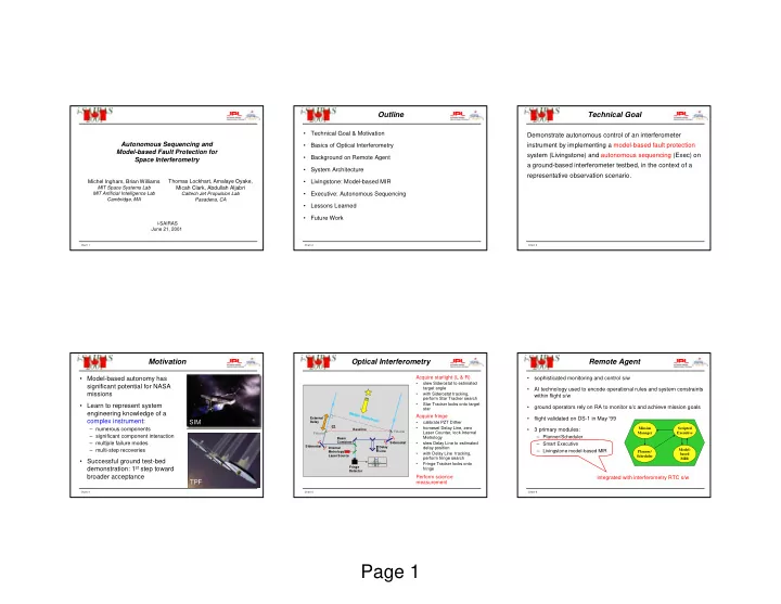
Outline
- Technical Goal & Motivation
- Basics of Optical Interferometry
- Background on Remote Agent
- System Architecture
- Livingstone: Model-based MIR
- Executive: Autonomous Sequencing
- Lessons Learned
- Future Work
Chart: 3
Technical Goal
Demonstrate autonomous control of an interferometer instrument by implementing a model-based fault protection system (Livingstone) and autonomous sequencing (Exec) on a ground-based interferometer testbed, in the context of a representative observation scenario.
Chart: 4
Motivation
- Model-based autonomy has
significant potential for NASA missions
- Learn to represent system
engineering knowledge of a complex instrument:
– numerous components – significant component interaction – multiple failure modes – multi-step recoveries
- Successful ground test-bed
demonstration: 1st step toward broader acceptance TPF SIM
Chart: 5
Optical Interferometry
Baseline Internal Metrology Laser Source Fiducial Fiducial Siderostat Siderostat External Delay
Stellar Wavefront
Delay Line
α
Fringe Detector Beam Combiner
Acquire starlight (L & R)
- slew Siderostat to estimated
target angle
- with Siderostat tracking,
perform Star Tracker search
- Star Tracker locks onto target
star
Acquire fringe
- calibrate PZT Dither
- homeset Delay Line, zero
Laser Counter, lock Internal Metrology
- slew Delay Line to estimated
delay position
- with Delay Line tracking,
perform fringe search
- Fringe Tracker locks onto
fringe
Perform science measurement
Chart: 6
Remote Agent
integrated with interferometry RTC s/w
- sophisticated monitoring and control s/w
- AI technology used to encode operational rules and system constraints
within flight s/w
- ground operators rely on RA to monitor s/c and achieve mission goals
- flight validated on DS-1 in May ‘99
- 3 primary modules:
– Planner/Scheduler – Smart Executive – Livingstone model-based MIR
Model- based MIR Mission Manager Scripted Executive Planner/ Scheduler