Optimum product quality thanks to correct spreader roll parameter - - PDF document

optimum product quality thanks to correct spreader roll
SMART_READER_LITE
LIVE PREVIEW

Optimum product quality thanks to correct spreader roll parameter - - PDF document

Finishing W. Flass, A. Giovannelli * Optimum product quality thanks to correct spreader roll parameter settings In Paper Industry spreader rolls are indispensable. They remove or The roll cores may be made of aluminium, steel or CFRP. They are


slide-1
SLIDE 1

Weekly Newspaper for Paper Production 11/12 · 2005

Finishing

  • W. Flass, A. Giovannelli *

Optimum product quality thanks to correct spreader roll parameter settings

In Paper Industry spreader rolls are indispensable. They remove or prevent incorrect wrinkles thus e.g. damaging the paper, creating an imprecise paint application or causing a paper roll to be 'curly'.

There are 2 spreader roll systems which are being commonly

  • used. Bowed rolls - also affectionately named "banana rolls" -

and the Lüraflex rolls, also known as "lamellar spreader rolls".

Rullo curvo

Bowed spreader roll Lüraflex spreader roll

  • Fig. 1: Spreader roll systems

The first system is based on a bowed roll that mechanically spreads the paper in the centre. This kind of rolls consists of numerous small inner rolls rotating on an axle. The radius of these spreader rolls can be adjusted and, depending on the type, the bow also is adjustable. Due to this option, the paper can be more or less expanded. The banana rolls often need a drive, a defined pre-travel and slowing-down distance as well as a defined wrapping angle. The second system is the "lamellar spreader roll" In the following, this principle will be explained in detail. For paper finishing, spreader rolls are implemented in e.g. cross cutting systems and in off-line calenders. The following text refers to the experience regarding spreader rolls at m-real Berg. Gladbach (formerly Zanders), Norske Skog Walsum (formerly Haindl) and Stora Enso Kabel.

Role core with floors and journals

Role core with fully mounted shaft

  • Fig. 2: Design of Lüraflex spreader rolls

* Dipl.-Ing: Winfried Flass, A. Giovannelli, Lüraflex-Walzen GmbH, Neuss, a.giovannelli@lueraflex.com Presentation given during the PTS presentation series “Paper Finishings”, November 2 – 3, 2004

The roll cores may be made of aluminium, steel or CFRP. They are either positioned inside with a fully mounted shaft or with shrunk, welded floors and fixed journals (Fig. 2). The cores for new spreader rolls are either manufactured precisely according to customer specifications or they are supplied by the customer as carriers. The spreader roll is completed by applying an elastic roll cover that is then equipped with a spreader roll

  • profile. Profile shape, cover quality and abrasiveness are

precisely adjusted to the final operating conditions, i.e. taking into consideration all mechanical stress as well as thermal and chemical exposure. As a rule, all Lüraflex spreader roll have a cylindrical shape with an even surface, except for the so-called separating spreader roll covers which have a slightly crowned profile.

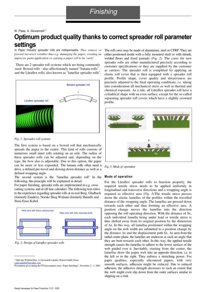
  • Fig. 3: Mode of operation

Mode of operation For the Lüraflex spreader rolls to function properly, the required tensile stress needs to be applied uniformly in longitudinal and transverse directions and a wrapping angle is required as effective area (Fig. 3).The tensile stress presses down the elastic lamellas of the profiles within the travelled distance of the wrapping angle. The lamellas are pressed down towards each other and thus forming an effective area. A position change moves the lamellas into the direction

  • pposing the roll operating direction. With the distance of Sx,

each individual lamella being under load or tensile stress is thus shifted away from its original position by the dimension

  • f ∆x. In this way, all lamellas positioned within the wrapping

angle on the web width are submitted to a position change by the distance ∆x and the displacement path Sx. As seen from the radial centre plane, the lamellas are undercut at such an angle that they are bent towards each other. In this way, the applied tensile strength causes the lamellas to adhere to the lower surface of the web guided over it. Inevitably, starting from the centre, the lamellas draw the paper web into an opposite direction, i.e. to the left or to the right. They enforce a stretching power. For paper qualities, especially siliconised papers, with very smooth surfaces, adhesion might be reduced. Due to reduced adhesion, the adhesive strength decreases to such an extent that the web might even slip down from the outer surfaces similar to slipping on a rink.

slide-2
SLIDE 2

Weekly Newspaper for Paper Production 11/12 · 2005

Finishing

Lamelle radiali Radial grooves

Spiral grooving

Micro profile

  • Fig. 4: Profile types

There are three main profile types, designated as A I, A II and A

  • III. The lamellas of all these profiles, as seen from the radial centre

plane, are undercut at opposing angles or have an angled undercut (Fig. 4). The profile design is determined by Lüraflex and is specified by the customer filling in a questionnaire and a specification sheet. Radial grooves

  • Fig. 5: Profile AI

The spreader roll profile AI has parallel, elastic lamellas with an angular undercut (Fig. 5). As seen from the roll centre, with

  • pposing angular positions. For this profile design, web travel is

not direction sensitive and thus can also be applied in reverse mode, i.e. feed and return. Depending on its abrasiveness, however, this spreader roll profile is subject to speed

  • limitations. There is danger that due to centrifugal forces,

lamellas outside the web width will straighten up at speeds higher than approx. 800 m per minute. If due to oscillation, this - paper web driven at high speed then laterally slides in web travel direction by a few tenths of a millimetre, this may result in sudden paper web breaks. This profile should be applied for papers with grammages of 40 g/m2 and more. For thinner papers, for tissue products and for "soft" paper qualities, there is danger of the web edges being drawn into the outer grooving area. The angled edges will not straighten up any more. They will then be fully folded and will lead to winding errors or deviations of the travelling web.

A II

Micro profile

  • Fig. 6: Profile AII

Profile A II is also called the micro profile (Fig. 6). Profile AII also consists of parallel cut-ins, approx. 0.5 mm wide, i.e. the surface is almost groove-free. This profile was mainly developed for the application in tissue production. Starting from the radial centre plane towards the edges, the 0.5 mm wide cut-ins get deeper. This is known as negative crowning. Due to the lamellas getting longer towards both roll ends, the

  • uter profile areas have longer lever arms making tilting and

deflecting via tensile strength easier. Since tensile strength applied to tissue products are usually much lower than for more tear-resistant papers, negative crowning optimises the functioning of the micro profile. During higher speeds, the lamellas on radial micro profiles also tend to straighten up outside the web width, which may result in interferences (paper web breaks

  • r

additional creation

  • f

wrinkles etc.).

A III

Spiral profile

  • Fig. 7: Profile AIII
slide-3
SLIDE 3

Weekly Newspaper for Paper Production 11/12 · 2005

3

Finishing

Profile A III consists of grooves with an angular undercut which however are not positioned in parallel but which are spiralling at the same pitch, starting from the radial centre plane towards the roll ends, to the left and to the right.(Fig. 7) With this profile design, the disagreeable effect of the web edges being fed into - the grooving area is avoided. The A III profile is a universal spreader roll profile that can be applied for almost all

  • materials. As a rule, the spiral profiles have one groove start. In

individual cases, however, the profile has several groove starts, e.g. two, three or four groove starts. With a higher number of groove starts, rolls running at low speeds are optimised since due to the higher groove pitch a 'longer distance' is being travelled during the same period of time. The correct division ratio of the circumferential groove starts on the radial centre plane determines the angular degree, i.e. 180° offset for a profile with two groove starts, 120° offset for a profile with three groove starts, 90° offset for a profile with four groove starts etc. In this way it is ensured that with consistent segment width the elastic resistance of the lamellas is generally smaller than the tensile strength. This is how the tensile strength is able to press down the lamellas or slide them towards each other thus creating a corresponding spreader effect. The profile A III / P. is a special design. It is a thread with a progressive angular undercut, i.e. the pitch per groove start is getting larger by a defined value x. The groove width stays the same whereas the segment width is increasing from groove start to groove start by the value x. This profile is applied for relatively wide paper webs of rather thin grammage, e.g. newspapers with a web width of more than 3000 mm and speeds up to 800-900 m/min. Due to the good adhesion values, the centre crinkles of these papers is smoothed out relatively fast to the sides. However, these crinkles are not smoothed out fast enough at the edges so that the paper might

  • buckle. Due to the higher pitch at the outer edges, compression

is avoided. It is much more expensive to produce this profile than a standard A III profile with continuous pitch. The reason for this is that additional grooves need to be applied outside the radial centre plane, at every new groove start with the segments getting wider towards the outside edges. In theory, this profile can be applied for thinner, more critical products with at times various traction forces applied over the entire web width, caused for instance by different moisture profiles throughout the cross sections.

  • Fig. 8: Cross cutters / Possible applications for spreader rolls

Cross cutters / Possible applications for spreader rolls Roll cutting as well as cross cutting requires a clean cut to achieve high winding quality and high format precision (Fig. 8). These prerequisites are to be met to guarantee smooth, wrinkle-free paper web feed. Lüraflex spreader rolls largely contribute to achieve this goal. A typical installation position in the unwind unit is the position of the first roll behind the unwind roll. The Lüraflex roll should be positioned as close as possible to the unwind unit. As a rule, in

  • rder to optimize web travel, these roles can be height

adjusted at one side by a defined value deviating from the axial centre plane. The elastic spreader roll profile supports these efforts by wrinkle-free web travel and, in particular for poor winding qualities, by taking in air, i.e. air suction, securely prevents the paper from floating on an air cushion out of contact with the spreader roll (Fig. 9).

  • Fig. 9: Cross cutters / Possible applications for spreader rolls

The Lüraflex spreader rolls are often used behind the unwinding unit to carry off multi-layer paper webs without creating wrinkles. The experience up to now showed that possible applications for coated papers and uncoated papers differ regarding the great variety of grammages and wrapping

  • angles. Uncoated papers with an overall grammage of up to

700 g are handled with success. Thus 7 layers of 100 g each can be handled. For coated papers the maximum grammage is 900 g, e.g., 8 layers of 110 g each. The wrapping angle for non- coated papers should not exceed 50 - 60°. For coated papers, maximum angles of 80-90° are recommendable. The reason for this is that at high wrapping angles, the tensile strength may cause the superimposed layers of uncoated papers to strongly interlock due to the relatively high friction. Since the individual layers have different circumferential speeds at continuous speed, individual layers may be overstretched

  • r torn off depending on the situation, i.e. errors that more
  • r less influence format precision. When meeting the above

requirements, however, Lüraflex spreader rolls can very well be used as an alternative to other spreader roll systems since it results in gentle, wrinkle-free web travel. Web travel is gentle because in contrast to bowed rolls, the cylindrical straight surface prevents overstretching in the centre part. Furthermore, Lüra-

slide-4
SLIDE 4

Weekly Newspaper for Paper Production 11/12 · 2005

Finishing

flex spreader rolls run without drive and are almost maintenance- free, bow adjustment and radius change are not applicable.

  • Fig. 10: Cross cutters / Possible applications for spreader rolls

Further typical installation positions in longitudinal and transversal slitters are placed upstream of the flattening and straightening unit (in front of the decurler) as well as upstream of the longitudinal slitter (in front of the circular blades). In the flattening / straightening unit a wrinkle-free paper web is fed to the decurler thus avoiding waste thanks to the use of the Lüraflex spreader roll (Fig. 10). Upstream of the longitudinal slitter, the spreader roll eliminates any wrinkles and creates a transversal tension force to the left and to the right supporting downstream separating. This effect can be further amplified via a slight crowning of the surface profile. In this case, we speak of so-called separating spreader rolls.

  • Fig. 11: Practical example: Paper mill Zanders, M-real Berg.- Gladbach

Practical example: Paper mill Zanders, M-real Berg. Gladbach In the Zanders paper mill, Bergisch-Gladbach, a total of 10 longitudinal and transversal web cutters from Jagenberg have been installed, 9

  • f

them synchronous cross cutters (SynchroQuerschneider) - 237-837 series. The latest system by Bielomatik-Jagenberg is the Synchro 844 sorting cross cutter. Papers with a grammage of 90–350 g/m2 are manufactured and cut, bilaterally coated papers (image printing papers for brochure and catalogue production)as well as papers with one-sided high gloss coating (Chromolux) for e.g. labels. In almost all cross cutters, Lüraflex spreader rolls have been implemented. The paper with up to 6 layers is being cut. In general, the first roll behind the unwinding unit is a Lüraflex spreader roll. Furthermore, all systems include a Lüraflex spreader roll upstream of the flattening / straightening unit and as last roll in front of the slitter. The new 844 system is an exception to the

  • rule. Here, the second roll upstream of the circular blades is a

Lüraflex spreader roll. The last roll upstream of the slitter is a bowed Kickers spread roller without rubber cover. According to the customer, it is advantageous that the roll is maintenance free as to setup changes such as bow adjustment and radius change. Another advantage mentioned is that the Lüraflex rolls run more smoothly than the banana rolls. Moreover, by taking in air, the Lüraflex spreader roll securely prevents the paper from floating

  • n an air cushion out of contact with the spreader roll. This is

valid for the profile applied here in A I (parallel surface profile) as well as for profile A III (spiral surface profile). No difference in effectiveness could be detected. Both profiles operate equally

  • well. The applied wrapping angles are between 30 and 70°,

depending on the installation position. Besides the fact that the spreader roll profile is maintenance-free, the customer states an additional centring effect and supports the straight running

  • f the paper webs. The oldest spread roll covers implemented

here, have been running for almost 7 years already without replacement, partly in multi-shift operation. According to the customer, the price being much lower than the price for bowed spreader rolls was crucial for the decision to implement the Lüraflex spreader roll.

  • Fig. 12: Offline calender / Possible applications for spreader rolls

Offline calender / Possible applications for spreader rolls In an offline calender (in most cases a supercalender), spreader rolls are used in great numbers. They differ according to their position (Fig. 12). Upstream of the infeed and downstream of the outfeed of the calender we find typical 'banana' rolls with bow adjustment and immersion depth adjustment. Uniroll rolls are to be found between the individual calender rolls. Uniroll rolls are three-part segmented inner rolls that only allow for unidirectional adjustment. At both positions, Lüraflex spreader rolls can be applied.

slide-5
SLIDE 5

Weekly Newspaper for Paper Production 11/12 · 2005

5

Finishing

A well-known problem of the Uniroll rolls in the supercalender is the overheating of the bearings. This can lead to different - gloss intensities, in the form of longitudinal stripes or it may lead to different moisture profiles. The latter becomes obvious via 'curly' paper webs and thus with improperly wound paper

  • rolls. During the last years, new self-aligning ball bearings have

been developed, reducing temperature rise. In order to be able to make use of the state-of-the-art technology, the old spherical roller bearings should be replaced. This, of course, requires time and money. In the following, by way of practical examples, we will present two different solutions:

  • Fig. 13: Practical example: Stora Enso, Werk Kabel

Practical example: Stora Enso, Werk Kabel The 12 roll calender is a Voith supercalender (formerly Kleinewefers). Here, coated papers between 38–50 g/m2 are calendered for gravure printing (magazines) (MWC 2 coatings per side and ULWC with 1 coating per side). The paper width is 7400 mm. Operating speed or maximum speed is 830 m/min. This system has no significant problem regarding overheated

  • bearings. Here, the company switched to the Lüraflex system for

financial reasons only (Fig. 13). For the time being, Stora Enso Kabel has 2 Lüraflex spreader rolls for the supercalender, a third one is currently being manufactured. At the moment, only one is being used - since 2001 on the

  • SK7. The other roll is currently being modified in the area of

the roll journals On the SK 7, a new concept regarding roll construction was applied, the basic idea being to invent a roll that can quickly and easily be installed in the operating SK system. Taking into account these facts, the CFRP core with inner bearings was chosen. Since the overall length is 8500 mm, it was not possible to use a

  • ne bearing axle. This problem was solved by applying two

bearings and one fixed steel shafts one each side. Since the diameter of the roll is very small (approx. 345 mm), the spreader effect was realized using a V profile (AIII) with two groove starts per side. The spreader roll is placed between calender rolls 8 and 9. The Uniroll rolls are made out of steel. They are partly equipped with self-aligning ball bearings with internal lubrication, showing a lower temperature rise than old spherical roller bearings. We do not know how many Uniroll rolls are equipped with self- aligning ball bearings.

On guide roll After guide roll Before guide roll

Temperature measurements clearly show the differences between both types of bearings and the Lüraflex roll system. These measurements have been taken on the paper - upstream of, on, and downstream of the roll - covering the entire width.

  • Fig. 15: Practical example: Stora Enso, Werk Kabel

The sharp temperature increases of the Uniroll roll with spherical - roller bearings is clearly visible (Fig. 15). Covering the entire web width, the paper web still maintains a constant temperature before getting into contact with the steel roll. On the steel roll, the temperature rises precisely at the positions of the bearings. The paper remains heated up even after leaving the steel roll.

  • Fig. 16: Practical example: Stora Enso, Werk Kabel

As expected, the new self-aligning ball bearings show no temperature rise (Fig. 16).

  • Fig. 14:

Practical example: Stora Enso, Werk Kabel

slide-6
SLIDE 6

Weekly Newspaper for Paper Production 11/12 · 2005

Finishing

  • Fig. 17: Practical example: Stora Enso, Werk Kabel Fig. 19: Practical example: Stora Enso, Werk Kabel

The Lüraflex roll does not show any temperature peaks either (Fig. 17).

  • Fig. 18: Practical example: Stora Enso, Werk Kabel

The last measurement was taken on a Uniroll roll with self- aligning ball bearing. No temperature rise could be detected here either (Fig. 18). During all measurings, the paper edges show a low

  • temperature. We assume that the heat can pass of more easily

at the edges than in the centre of the calender. Conclusion The price is the decisive reason for the implementation of a Lüraflex spreader roll (Fig. 19). The price of a new Uniroll three-part segmented roll with internal lubrication is 60% higher than that of a Lüraflex spreader roll, consisting of an inner CFRP core with a Lüraflex spreader roll rubber cover. When comparing both spreader roll systems, no relevant quality improvement can be detected. The old spherical roller bearings tend to have damaged sealings through which grease is lost that partly reaches and contaminates the paper web. Thanks to the new self-aligning ball bearings with internal lubrication this problem is solved. Compared to the Uniroll system, the Lüraflex spreader roll allows for more stable paper web travel. This is due to the cylindrical form of the Lüraflex spreader roll. The paper web lies on the entire roll width without any tension differences. With the Uniroll rolls, the edges are a little more 'slack' than in the centre. Practical example: Norske Skog, Walsum The 12 roll calender, SK6 (system 10) is a Voith Sulzer (formerly Sulzer-Escher Wyss) supercalender type nip-reliving calender with overhanging load compensation. Here, coated papers between 35–80 g/m2 are calendered for gravure printing (catalogues, magazines) with one coating per

  • page. The paper width is 7400 mm, the operating speed is

between 700–750 m/min, the maximum speed is around 1000 m/min. The initial moisture is approx. 6.5%, the output moisture is approx. 4.5% – 5.0%. Norske Skog had a huge problem with overheated bearings which lead to the problems described above. Differences in the moisture profile were detected. In the area

  • f the bearings, the paper had curled longitudinal stripes

leading to very unsatisfying winding results: circular buckles

  • n the paper roll.
  • Fig. 20: Practical example: Norske Skog, Walsum

The first measure taken was to cover the Uniroll rolls with a 5 mm rubber layer to achieve 'thermal insulation'. A temperature At of 5 – 8°C was then measured between steel and rubber covered roll (Fig. 20). Beginning of 2001, the company considered for the first time to implement a Lüraflex spreader roll to reduce temperature rises in the area of the bearings. For financial reasons, the company chose to cover the Uniroll roll with a Lüraflex spreader roll rubber profile. We received the dismounted Uniroll roll (i.e. 3 individual steel tubes) that we covered with our spreader roll profile. In this context, the V profile has been observed so that after assembly the spiral runs

Conclusion Lüraflex spreader roll 60 % Cost reduction

Improved guided web travel

Temperature results

UNIROLL - rolls made of steel UNIROLL - rolls with rubber cover UNIROLL - roll

slide-7
SLIDE 7

Weekly Newspaper for Paper Production 11/12 · 2005

Finishing

from one roll to another without being interrupted. The rubber was removed from the screwed connection as well as the grease nipples were to ensure future lubrication.

  • Fig. 21: Practical example: Norske Skog, Walsum

Compared to the rubber-covered Uniroll rolls, an additional improvement of 3 – 4°C At was achieved (Fig. 21)

  • Fig. 22: Practical example: Norske Skog, Walsum

The first roll was implemented in August 2001 between calender rolls 10 and 11. Five months later, the second spreader roll followed. It was installed between calender rolls 1 and 2 (Fig. 22). After 5 months already, there were cracks on the surface of the first roll. Investigations showed that the direct atmosphere contained a high percentage of ozone gas. This is caused by the electrically charged paper web. In this position between calender rolls 10 and 11, the paper is very dry. We detected sparks due to electrically charged paper. These sparks, when coming into contact with oxygen in the air, create ozone. The rubber quality applied is a material developed for the paper industry. However, it is not ozone-resistant. For this special application we developed a new, ozone-resistant quality. The implemented spreader roll that is covered with the new mixture, has been running since April 2002 without any complaints. We detected this phenomenon in this system only. Other rolls in the very same position but in other calenders did not show any similar effects. The second Lüraflex spreader roll between calender rolls 1 and 2 without ozone-resistant quality, operates without any problem.

Conclusion

UNIROLL rolls with Lüraflex rubber profile UNIROLL rolls with other rubber profile Improvement of 1 - 2% regarding the moisture profile

  • Fig. 23: Practical example: Norske Skog, Walsum

Conclusion: Covering the Uniroll rolls with a rubber profile lead to an improvement. In addition, covering the Uniroll rolls with the Lüraflex spread roller rubber profile lead to an improved moisture profile of 1-2% (Fig. 23). The measurement was carried out in the area of the bearings on the paper side. For the time being, 20 of the 22 Uniroll rolls have an even rubber profile and 2 of them have a spreader roll profile. Lüraflex - The company Produces rolls, spreader rolls, special tubes for paper, rubber, steel, aluminium, textile and food industry. 30 employees. The rolls produced can have a length of up to 10 m and a diameter

  • f 1.5 m.

Thanks to CNC turning and grinding machines, the company is able to produce (mill, cut or via thermocutter blades) almost any profile and to grind concave and convex (crowned)

  • surfaces. With currently 14 sales representatives, Lüraflex is

present in many countries of the world. For the paper industry in particular, Lüraflex produces e.g., coater rolls, backing rolls, plaster rollers, tambours and felt guiding rolls (Fig. 24).

Dimensions: Length 9500 mm Diameter 1500 mm Coater rolls Backing rolls Tambours Plaster rollers Felt guiding rolls

  • Fig. 24: Presentation by Lüraflex

For more information: Lüraflex-Walzen GmbH, Heerdterbuschstr. 12, D-41460 Neuss, Phone +49 2131/ 12568-0, Fax: +49 2131/ 12569-30 E-mail: service@lueraflex.com www.lueraflex.com

Temperature results

UNIROLL rolls with other rubber profile UNIROLL rolls with Lüraflex rubber profile