operational amplifiers
play

Operational amplifiers ENGR 40M lecture notes August 7, 2017 - PDF document

Operational amplifiers ENGR 40M lecture notes August 7, 2017 Chuan-Zheng Lee, Stanford University V DD v n i n v o v p + i p V DD An operational amplifier , or op-amp , is a device that outputs the difference between its two inputs, v


  1. Operational amplifiers 
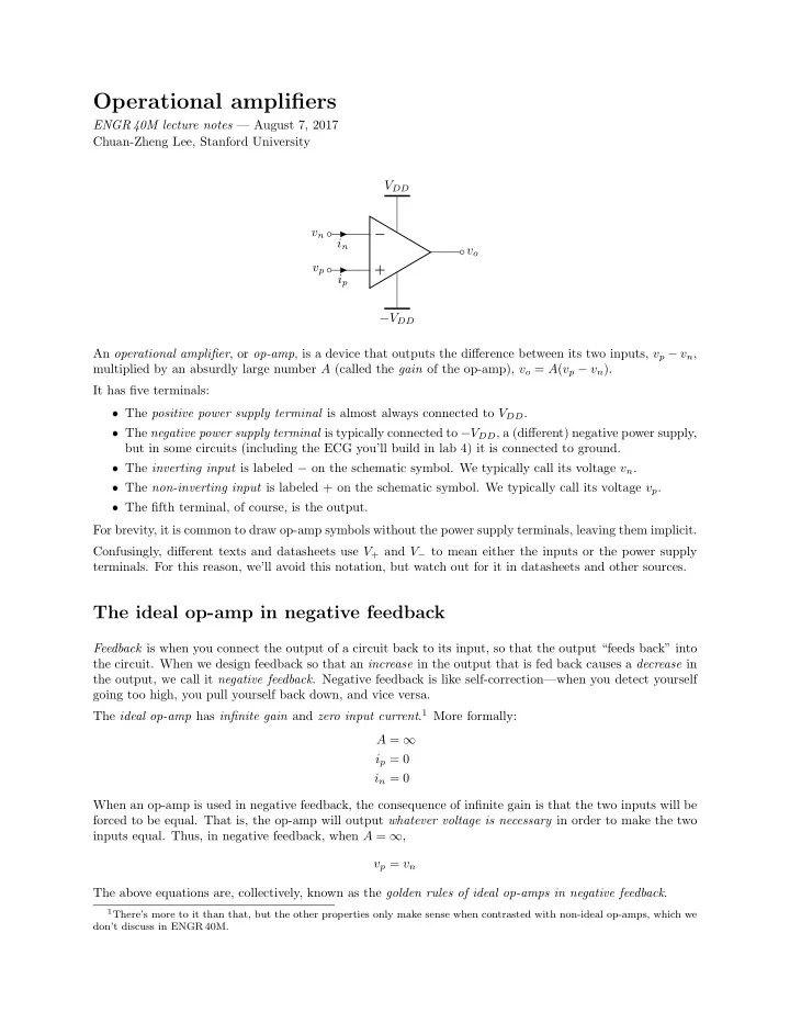
ENGR 40M lecture notes — August 7, 2017 Chuan-Zheng Lee, Stanford University V DD v n − i n v o v p + i p − V DD An operational amplifier , or op-amp , is a device that outputs the difference between its two inputs, v p − v n , multiplied by an absurdly large number A (called the gain of the op-amp), v o = A ( v p − v n ). It has five terminals: ❼ The positive power supply terminal is almost always connected to V DD . ❼ The negative power supply terminal is typically connected to − V DD , a (different) negative power supply, but in some circuits (including the ECG you’ll build in lab 4) it is connected to ground. ❼ The inverting input is labeled − on the schematic symbol. We typically call its voltage v n . ❼ The non-inverting input is labeled + on the schematic symbol. We typically call its voltage v p . ❼ The fifth terminal, of course, is the output. For brevity, it is common to draw op-amp symbols without the power supply terminals, leaving them implicit. Confusingly, different texts and datasheets use V + and V − to mean either the inputs or the power supply terminals. For this reason, we’ll avoid this notation, but watch out for it in datasheets and other sources. The ideal op-amp in negative feedback Feedback is when you connect the output of a circuit back to its input, so that the output “feeds back” into the circuit. When we design feedback so that an increase in the output that is fed back causes a decrease in the output, we call it negative feedback . Negative feedback is like self-correction—when you detect yourself going too high, you pull yourself back down, and vice versa. The ideal op-amp has infinite gain and zero input current . 1 More formally: A = ∞ i p = 0 i n = 0 When an op-amp is used in negative feedback, the consequence of infinite gain is that the two inputs will be forced to be equal. That is, the op-amp will output whatever voltage is necessary in order to make the two inputs equal. Thus, in negative feedback, when A = ∞ , v p = v n The above equations are, collectively, known as the golden rules of ideal op-amps in negative feedback . 1 There’s more to it than that, but the other properties only make sense when contrasted with non-ideal op-amps, which we don’t discuss in ENGR 40M.

  2. Output saturation Naturally, an op-amp can only output voltages contained within the range of its power supply. (In fact, most op-amps can’t quite hit that range—they stop at about 1 V to 2 V before the power supply voltage, depending on the op-amp and circuit.) When the output voltage implied by the circuit would exceed the possible range, the op-amp is said to saturate , and it just outputs its maximum or minimum possible voltage instead. We often call the supply voltages the rails . When op-amp output saturation causes the signal to be cut off close to the rails, we say that the signal is clipped . v o ( t ) desired output V DD actual output t − V DD clipping Practical matters Is the gain really infinite? Obviously, no op-amp actually has infinite gain. But in practice, the gain of most op-amps is high enough that, in negative feedback, v p = v n is a very reliable approximation. Moreover, the gain of op-amps typically isn’t precisely specified—the LM4250CN, for example, merely guarantees that it’s at least 25 000 (with no upper bound). The usefulness of an op-amp isn’t so much the high gain, as it is that a ridiculously high gain allows us to use negative feedback to make circuits with very predictable gain. What’s inside an op-amp? An op-amp is implemented with lots of transistors. (Recall that transistors can be used as either amplifiers or switches, though we only studied the latter.) The precise number varies from model to model, but as an example, the LM4250CN (which you’ll use in lab 4) has eighteen. Examples The following examples are all extremely common circuits. Example 1 (Inverting amplifier) . The circuit below is known as an inverting amplifier . R 2 v in − R 1 v out + The gain of this circuit can be shown to be v out = − R 2 . v in R 1 2

  3. This means that the output is a multiple of − R 2 R 1 times its input. For example, if R 2 = 4 kΩ and R 1 = 1 kΩ, then the gain would be − 4. If you put a 1 V peak-to-peak (1 Vpp) sine wave into the input, the output would look like this: 2 v out ( t ) 0 . 5 t − 0 . 5 v in ( t ) − 2 (Why do you think it’s called an inverting amplifier?) Example 2 (Non-inverting amplifier) . The circuit below is known as a non-inverting amplifier . R 2 − R 1 v out v in + Show that the gain of this circuit is v out = 1 + R 2 . v in R 1 Exercise 1. Consider a non-inverting amplifier with R 1 = 10 kΩ and R 2 = 90 kΩ. The op-amp is supplied with V DD = 12 V to its positive power supply terminal, and − V DD = − 12 V to its negative power supply terminal, and the op-amp’s output saturates at 1 . 5 V from the power supplies. You provide the circuit with an input v in ( t ) that looks like this: v in ( t ) 2 1 t (s) 1 2 3 4 − 1 Sketch the output v out ( t ). 3

  4. Example 3 (Voltage follower) . The circuit below is known as a voltage follower or voltage buffer . − v out v in + Find the gain of this circuit. What do you think its purpose is? Hint: A buffer , in several engineering disciplines (and by extension, more generally in life), is something that isolates or separates two things, to minimize the influence or impact of one on the other. Why is this circuit called a buffer? Exercise 2. The non-inverting amplifier in Example 2 is only capable of gains greater than 1. How would you design a circuit whose gain is positive and less than 1, but whose output does not depend on the load resistance ? Example 4 (Differential amplifier) . The circuit below is known as a differential amplifier . R 2 v 1 − R 1 v out v 2 + R 1 R 2 Show that the output of this circuit is given by v out = R 2 ( v 2 − v 1 ) . R 1 Remark. This sounds like it might be really useful, but notice that this circuit draws current from the inputs. In many applications (for example, an electrocardiogram), this might affect what you’re trying to measure. 4

Download Presentation
Download Policy: The content available on the website is offered to you 'AS IS' for your personal information and use only. It cannot be commercialized, licensed, or distributed on other websites without prior consent from the author. To download a presentation, simply click this link. If you encounter any difficulties during the download process, it's possible that the publisher has removed the file from their server.

Recommend


More recommend