NUMERICAL ANALYSIS OF THE EFFECT OF PARTICLE ARRANGEMENT ON - - PDF document

numerical analysis of the effect of particle arrangement
SMART_READER_LITE
LIVE PREVIEW

NUMERICAL ANALYSIS OF THE EFFECT OF PARTICLE ARRANGEMENT ON - - PDF document

18 TH INTERNATIONAL CONFERENCE ON COMPOSITE MATERIALS NUMERICAL ANALYSIS OF THE EFFECT OF PARTICLE ARRANGEMENT ON MECHANICAL BEHAVIOR AND PARTICLE DAMAGE IN METAL MATRIX NANOCOMPOSITES E. Law, S.D. Pang *, S.T. Quek Department of Civil and


slide-1
SLIDE 1

18TH INTERNATIONAL CONFERENCE ON COMPOSITE MATERIALS

1 Introduction The spatial distribution of reinforcement particles has a significant effect on the mechanical response and damage evolution of metal matrix composites (MMCs). It is observed that particle clustering leads to higher flow stress, quicker and earlier particle damage, as well as lower overall failure strain. On the other hand, regular microstructure results in the highest strength [1, 2]. In recent years, experimental studies have shown that reducing the size of particles to the nanoscale dramatically increases the mechanical strength of MMCs even at low particle volume fractions. This is due to the higher plastic constraint in the matrix as well as activation of strengthening mechanisms

  • perating

at the nanoscale [3]. However, the effect of particle distribution on the mechanical response and particle damage in these metal matrix nanocomposites (MMNCs), which may be different from that

  • bserved in normal MMCs, has not been widely
  • explored. In this paper, this effect will be

investigated numerically using discrete dislocation simulations because size effects must be considered in the modeling of MMNCs [4]. 2 Discrete Dislocation Formulation The discrete dislocation plasticity framework used in this study follows closely the formulation developed by Van der Giessen and Needleman [5]. The nanocomposite is considered as a linear elastic body which contains elastic particles, with a distribution

  • f dislocations which glide along pre-determined

slip planes in the matrix. Constitutive relations are used to describe the motion, nucleation and annihilation of dislocations. Firstly, a dislocation will glide along its slip plane with its velocity directly proportional to the resolved shear stress acting on the dislocation. Obstacles to dislocation motion modeled as fixed points on a slip plane are distributed randomly in the matrix to account for the effects of small precipitates or impurities in blocking

  • slip. A dislocation moving towards an obstacle or

impurity will initially be pinned at the obstacle, after which it will be released when the resolved shear stress on the dislocation exceeds the strength of the

  • bstacle τobs. Secondly, new dislocation pairs are

generated by simulating Frank-Read sources. Thirdly, annihilation of two opposite dislocations

  • ccurs when they are within a material-dependent,

critical annihilation distance.

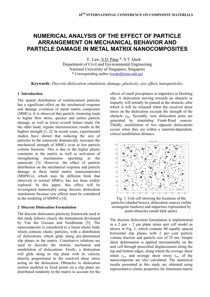
  • Fig. 1. Unit cell showing the locations of the

particles (shaded boxes), dislocation sources (white rectangular markers) and impurities represented by point obstacles (small dark spots). The discrete dislocation formulation is implemented in a 2 μm × 2 μm plane strain unit cell model as shown in Fig. 1, which contains 80 equally spaced horizontal slip planes with 2 per cent particle volume fraction and particle size of 25 nm. Simple shear deformation is applied incrementally on the unit cell through prescribed displacements along the top and bottom edges, along which the average shear strain γave and average shear stress τave of the nanocomposite are also calculated. The numerical results presented in this study are obtained using representative elastic properties for aluminum matrix

NUMERICAL ANALYSIS OF THE EFFECT OF PARTICLE ARRANGEMENT ON MECHANICAL BEHAVIOR AND PARTICLE DAMAGE IN METAL MATRIX NANOCOMPOSITES

  • E. Law, S.D. Pang *, S.T. Quek

Department of Civil and Environmental Engineering National University of Singapore, Singapore

* Corresponding author (ceepsd@nus.edu.sg)

Keywords: Discrete dislocation simulation, damage, plasticity, size effect, nanoparticles.

slide-2
SLIDE 2

and silicon carbide reinforcement nanoparticles; these material properties and various parameters used to describe dislocation processes in the constitutive relations follow that in Law et al. [6]. The mean overall response is computed using many different realizations

  • f

dislocation source, impurities and particle distributions since the overall response is highly dependent on these distributions. 3 Effect of Particle Arrangement on Overall Response of MMNCs with Undamaged Particles

  • Fig. 2 shows that regular rectangular and non-

clustered random particle arrangements result in the lowest and highest flow stress, respectively. This is because the number of slip planes blocked by the particles is minimized for the rectangular arrangement and there are many large veins of unreinforced matrix as shown in Fig. 3(a). Dislocations can move relatively easily with little hindrance on the many unobstructed slip planes. On the other hand, most slip planes are blocked by particles when the arrangement is well-dispersed as shown in Fig. 3(b). Dislocations unable to bypass the particles will form many dislocation pile-ups, which retard the generation of new dislocations and hinder the motion

  • f

existing dislocations. Impediment to dislocation motion increases the flow stress of the metallic nanocomposite. Fig. 2 also shows that a highly clustered particle arrangement (the degree of clustering is measured using the nearest-neighbor index (NNI), with smaller NNI indicating greater degree of clustering) produces lower flow stress compared to non-clustered random arrangement because there are more unobstructed slip planes in the matrix, as shown in Fig. 3(c). On the other hand, a mildly clustered particle arrangement only results in minor reduction in the flow stress since most slip planes are still blocked by the particles as shown in Fig. 3(d).

5 10 15 20 25 30 35 40 45 50 0.0 0.1 0.2 0.3 0.4 0.5 0.6 0.7 0.8 0.9 1.0 1.1 γ ave (%) Average shear stress, τ ave (MPa) Rectangular - NNI = 0.963 Random - NNI = 0.773 Mildly clustered - NNI = 0.581 Highly clustered - NNI = 0.308 0% particle Mean response τ particle = 1000 MPa

  • Fig. 2. Mean overall response of MMNC with

undamaged particles for different particle arrangements.

  • Fig. 3. Distribution of dislocations (+ and ×) and

particles (shaded boxes) at γave = 1.05% for (a) regular rectangular, (b) non-clustered random, (c) highly clustered (NNI = 0.308), and (d) mildly clustered (NNI = 0.581) particle arrangements. (a) (b) (c) (d)

slide-3
SLIDE 3

4 Effect of Particle Arrangement on Overall Response of MMNCs with Damaged Particles

  • Fig. 4(a) shows that the effect of particle damage on

the mean overall response of the nanocomposite is insignificant for a rectangular arrangement of

  • particles. This is because few dislocations are

impeded by the particles, hence only a small fraction

  • f particles is damaged and there is little change to

the sequence of dislocation processes and the final distribution of dislocations in the matrix as shown in

  • Figs. 3(a) and 5(a). The same trend is observed for

the nanocomposite with highly clustered particle arrangement, in which particle damage results in

  • nly a minor reduction in the flow stress and degree
  • f hardening as shown in Fig. 4(b). On the other

hand, the effect of particle damage on the mean

  • verall response is more significant for mildly

clustered and random particle arrangements as shown in Figs. 4(c) and 4(d), respectively. As these particle arrangements are more effective in blocking the motion

  • f

dislocations, many impeded dislocations are suddenly released upon particle

  • failure. Hence, particle damage results in fewer

dislocation pile-ups in the matrix which is evident when comparing Fig. 3(b) with Fig. 5(b). This leads to lower flow stress and degree of hardening when particle failure occurs. Figs. 4(b) and 4(c) show that the flow stress at applied shear strain γave = 1.0% for the case with particle fracture strength 200 MPa is approximately 5 and 15 per cent lower, respectively, compared to the case with no particle damage (in which fracture strength is 1000 MPa) for highly clustered and mildly clustered particle arrangements. Due to the increased efficiency in impeding the motion of dislocations, the average stresses within the particles in non-clustered random and mildly clustered particle arrangements are also higher compared to that in regular rectangular and highly clustered arrangements. Consequently, particle damage begins earlier and the fraction of damaged particles is also higher in these cases as shown in

  • Fig. 6. A greater fraction of particle damage must be

reached in these particle arrangements before the weakest path for localization of dislocation activity can be found. Also, as shown in Figs. 5(c) and 5(d) not all particles in a cluster will be damaged. The

  • utermost particles will tend to fail first because

they are under higher stresses due to the pile up of dislocations, whereas inner particles will be damaged later after the dislocations have bypassed the damaged periphery particles and begin to pile up against the inner particles. The results here are in slight contrast to that

  • bserved in conventional MMCs in which the flow

stress and fraction of damaged particles increase with degree of clustering [1]. This is because the dominant strengthening mechanism in MMNCs is impediment of dislocation motion, while load transfer from matrix to particles (i.e. constraint on deformation of the matrix surrounding the particles) governs the response of conventional MMCs.

5 10 15 20 25 30 35 40 45 50 0.0 0.1 0.2 0.3 0.4 0.5 0.6 0.7 0.8 0.9 1.0 1.1 γ ave (%) Average shear stress, τ ave (MPa) τ particle = 200 MPa τ particle = 1000 MPa 0% particle Mean response Regular rectangular arrangement 5 10 15 20 25 30 35 40 45 50 0.0 0.1 0.2 0.3 0.4 0.5 0.6 0.7 0.8 0.9 1.0 1.1 γ ave (%) Average shear stress, τ ave (MPa) τ particle = 200 MPa τ particle = 1000 MPa 0% particle Mean response Highly clustered arrangement - NNI = 0.308 5 10 15 20 25 30 35 40 45 50 0.0 0.1 0.2 0.3 0.4 0.5 0.6 0.7 0.8 0.9 1.0 1.1 γ ave (%) Average shear stress, τ ave (MPa) τ particle = 200 MPa τ particle = 1000 MPa 0% particle Mean response Mildly clustered arrangement - NNI = 0.581 5 10 15 20 25 30 35 40 45 50 0.0 0.1 0.2 0.3 0.4 0.5 0.6 0.7 0.8 0.9 1.0 1.1 γ ave (%) Average shear stress, τ ave (MPa) τ particle = 200 MPa τ particle = 1000 MPa 0% particle Mean response Uniform random arrangement

  • Fig. 4. Mean overall response of MMNC with

different particle fracture strength for (a) regular rectangular, (b) highly clustered (NNI = 0.308), (c) mildly clustered (NNI = 0.581), and (d) non- clustered random particle arrangements. (a) (b) (c) (d)

slide-4
SLIDE 4
  • Fig. 5. Distribution of dislocations and particles at

γave = 1.05% for (a) regular rectangular, (b) non- clustered random, (c) highly clustered (NNI = 0.308), and (d) mildly clustered (NNI = 0.581) particle arrangements. Intact particles are denoted by shaded boxes while damaged particles are represented by blanks; fracture strength of particles is 200 MPa.

0.00 0.04 0.08 0.12 0.16 0.20 0.0 0.1 0.2 0.3 0.4 0.5 0.6 0.7 0.8 0.9 1.0 1.1 γ ave (%) Fraction of particles damaged Rectangular - NNI = 0.963 Random - NNI = 0.773 Mildly clustered - NNI = 0.581 Highly clustered - NNI = 0.308 Mean response, τ particle = 200 MPa

  • Fig. 6. Fraction of damaged particles in MMNC with

particle fracture strength τparticle = 200 MPa for different particle arrangements. 5 Conclusions The flow stress for metallic nanocomposites with undamaged particles is lowest for rectangular and highly clustered particle arrangements while non- clustered random and mildly clustered arrangements result in higher flow stress. The effect of particle damage

  • n

the

  • verall

response

  • f

the nanocomposite is also more significant for random and mildly clustered particle arrangements, in which particle damage begins earlier and the fraction of damaged particles is higher, compared to rectangular and highly clustered arrangements. References

[1] J. Segurado, C. González and J. LLorca. “A numerical investigation of the effect of particle clustering

  • n

the mechanical properties

  • f

composites”. Acta Materialia, Vol. 51, pp 2355- 2369, 2003. [2] L. Mishnaevsky Jr., K. Derrien, D. Baptiste. “Effect

  • f microstructure of particle reinforced composites on

the damage evolution: probabilistic and numerical analysis”. Composites Science and Technology, Vol. 64, pp 1805-1818, 2004. [3] S.C. Tjong. “Novel nanoparticle-reinforced metal matrix composites with enhanced mechanical properties”. Advanced Engineering Materials, Vol. 9, pp 639-652, 2007. [4] S. Groh, B. Devincre, L.P. Kubin, A. Roos, F. Feyel and J.L. Chaboche. “Size effects in metal matrix composites”. Materials Science and Engineering A,

  • Vol. 400-401, pp 279-282, 2005.

[5] E. Van der Giessen and A. Needleman. “Discrete dislocation plasticity: a simple planar model”. Modelling and Simulation in Materials Science and Engineering, Vol. 3, pp 689-735, 1995. [6] E. Law, S.D. Pang and S.T. Quek. “Discrete dislocation analysis of the mechanical response of silicon carbide reinforced aluminum composites”. Composites Part B: Engineering, Vol. 42, No. 1, pp 92-98, 2011.

(b) (c) (d) (a)