North Dakota Missile Road Gravel Stabilization with Determine if - - PDF document

north dakota missile road gravel stabilization with
SMART_READER_LITE
LIVE PREVIEW

North Dakota Missile Road Gravel Stabilization with Determine if - - PDF document

5/14/2020 Presentation Objectives North Dakota Missile Road Gravel Stabilization with Determine if the MT missile road gravel stabilization process will work well with North Dakota specifications and gravel Calcium Chloride Determine if


slide-1
SLIDE 1

5/14/2020 1

North Dakota Missile Road Gravel Stabilization with Calcium Chloride

Stephen Monlux, LVR Consultants LLC, Missoula MT stevemonlux@gmail.com 406-544-1919

Note that the information provided in this presentation was prepared for tech transfer

  • nly and does not supersede any contract requirements.

Also, the interpretation of plans and specifications in this document come from a person with no contract authority.

Presentation Objectives

  • Determine if the MT missile road gravel stabilization process will work well

with North Dakota specifications and gravel

  • Determine if chloride stabilization is cost effective
  • Transfer knowledge developed from 10 years of experience from the

MTDAR program

  • Ensure that all become aware of problems that can develop during

construction

  • Challenge local Contractors and County road crews to determine better

ways to do chloride stabilization

  • Stimulate group discussion and obtain feedback
  • Develop a plan that will complete the contract in a timely and cost effective

manner.

2

Presentation Resources

  • FHWA 2017 Chloride Stabilization Report (MT Missile Roads)
  • Braun Intertec 3-25-2020 Report on G-11 and G-08N
  • NDLTAP 2017-19 “Clay is the Glue”
  • IDLTAP 2002-2019 “Gravel Road Design and Maintenance”
  • MillRazor Manual 2018 “User Guide for Stabilized Gravel”
  • One Page Guides for Adding Clay
  • 2017 - Adding Clay with Belly Dump Trucks
  • 2019 - Adding Clay with Water trucks
  • Spokane Co 2019
  • “Gravel Road Improvement Plan” and
  • “Guidelines for Gravel Road Testing Projects”
  • USAF Workshops 2008 “Malmstrom Missile Road QA/QC for Chloride Stabilization”

3

Presentation Modules/Outline

  • Introduction
  • 1 Expected Gravel Performance
  • 2 Performance Measurements
  • 3 Construction Equipment
  • 4 Construction Procedure
  • 5 Quality Control and Quality Assurance
  • 6 Maintenance of Chloride Stabilized Gravel
  • 7 Conclusions

4

Introduction

  • Chloride Stabilization Benefits:
  • Less rock loss per year: ½” to 1/8” (MT

Missile Road study after 6 years)

  • Less blading costs by 65%
  • Other Benefits: Saves gravel resources,

increases road user safety, less vehicle maintenance, less dust, greater fuel economy, improved public relations

  • Problems:
  • Higher initial cost, better gravel, clay
  • Process requires attention to details
  • Purpose of Presentation: Explain details

5

West Tensleep Road, Big Horn NF 2006

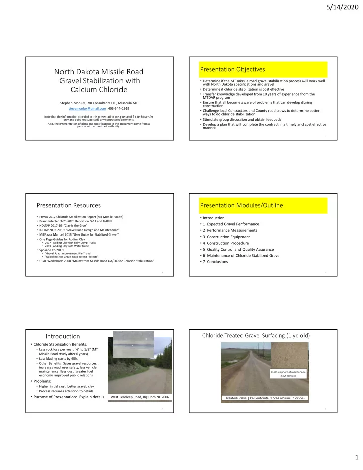
Chloride Treated Gravel Surfacing (1 yr. old)

Close-up photo of road surface in wheel track

Treated Gravel (3% Bentonite, 1.5% Calcium Chloride)

6

slide-2
SLIDE 2

5/14/2020 2

Module 1: Expected Performance

  • Will likely be less effective than MTDAR because gravel gradation, PI

and construction practices.

  • List of reasons why lower performance
  • Sandy gradations with lower % Fracture wash board and ravel
  • Low clay contents (plasticity index) allow chloride leaching
  • Construction process more complicated, treatment depth control less precise

* Consequences of lower performance Greater performance problems (dust, washboards, raveling) More frequent blading More frequent gravel replacement

7

10 20 30 40 50 60 70 80 90 100

0.01 0.1 1 10 100

Gravel Quality

#200 #16 #4 #40 3/4”

Sieve Sizes Percent Passing

Wash boarding Problems

Rutting Problems

Sieve Size Spec 3/4 inch 100 3/8 inch 67-85

  • No. 4

48-68 No 16 25-42

  • No. 40

17-30 No 200 8-18 4-10 75 Gradation % Fracture Plasticity Index

Good Gravel Spec 3/8” Raveling Problems Good Performance if enough clay (PI)

8

Gradation Summary Graphs (Site D-3 and C-10, New Gravel)

9

Important “Take Aways” for New Gravel

  • Somewhat more dusting, wash boarding and blading than most Montana missile

roads

  • P200 + PI = 21 is lower  low “binder” more raveling, dusting
  • Gradation has more sand, higher voids  more chloride leaching, more dusting, shorter

gravel life

  • Adding 1.5% bentonite during maintenance blading will:
  • Reduce blading
  • Reduce dusting
  • Increase chloride life
  • Increase gravel life
  • Suggested method for adding bentonite  water truck with bentonite slurry
  • The sample used for the “modified” density test should have a similar gradation

and PI to the average shown on the previous slide

10

Gradation Summary Graphs (Sites G-11, G-08N Old Gravel)

Std mm mm0.45 High Low 1 2 3 4 5 6 7 8 9 10 11 12 13 14 15 16 17 18 19 20 ? 2 3 4 5 1" 25.000 4.257 100 100 100 100 100 100 100 100 100 100 100 100 100 100 100 100 100 100 100 100 100 100 100 100 100 100 100 100 3/4" 19.000 3.762 100 70 99 97 99 96 97 95 98 99 99 99 99 98 95 97 96 95 98 99 97 98 97 97 98 98 98 98 1/2" 12.500 3.116 90 50 92 88 93 86 87 87 88 94 95 90 90 91 88 91 88 88 90 93 89 90 90 91 91 90 92 90 #4 4.750 2.016 75 38 76 76 75 68 70 74 75 83 82 73 75 78 72 78 70 72 74 78 73 76 73 76 76 75 77 75 #8 2.360 1.472 62 22 64 69 62 58 60 63 66 76 72 63 63 67 63 67 61 61 61 68 64 67 63 65 67 64 68 65 #30 0.600 0.795 45 12 43 53 45 39 40 42 45 55 49 43 39 43 41 44 40 40 40 46 45 45 42 43 45 42 47 44 #200 0.075 0.312 15 7 11.0 16.0 15.0 12.0 12.9 12.6 12.2 15.0 15.4 13.1 8.7 13.2 14.8 15.5 13.8 14.0 14.5 15.7 13.8 12.8 12.0 13.0 14.0 14.0 14.0 13.6 9 4 Sieve Size Spec 816.02 Class 13M Mod. Type 1 Average Plasticity Existing Gravel on Sites G11 & G08N (Sample MP start from North) MP 7 MP 2 MP 3 MP 4 MP 5 MP 6 MP 8 MP 9 MP 10 MP 11 MP ?

10 20 30 40 50 60 70 80 90 100 0.010 0.100 1.000 10.000 100.000 Percent Passing Sieve Size, mm

Site G11 & G08N Avg and ND DOT 13M Modified Type 1 Spec

High Spec Limit Low Spec Limit Average Gradation 20 40 60 80 100 0.010 0.100 1.000 10.000 100.000 Percent Passing Sieve Size

Site G11 & G08N Gradations of Existing Gravel

Series1

Std mm High Low 1" 25.000 100 100 1/2" 12.500 85 75 #4 4.750 50 40 #10 2.000 40 25 #40 0.425 25 15 #200 0.075 14 8 10 4 Sieve Size 2019 MT DAR Spec Target Limits (Table 703-3A) Plasticity

20 40 60 80 100 0.010 0.100 1.000 10.000 100.000 Percent Passing Sieve Size, mm

Site G11 & G08N Gradation Avg & MT DAR Spec

High Spec Limit Low Spec Limit Average Gradation

11

Important “Take Aways” for Old Gravel

  • Significantly more dusting, wash boarding and blading than all the Montana missile roads
  • P200 + PI = 14 is much lower  low “binder” more raveling, dusting
  • Gradation has much more sand, higher voids  rapid chloride leaching, more dusting, shorter

gravel life

  • If dust abatement is needed only apply surface applications
  • Adding 3% bentonite during maintenance blading will:
  • Reduce blading and dusting to some extent
  • Increase chloride and gravel life to some extent
  • May cause rutting and sloppy road surfaces in the spring – CBR/chloride leaching testing is

suggested confirm 3% bentonite addition

  • Suggested method for adding bentonite  Belly dump with gravel containing high

concentrations of dry bentonite

  • The sample used for the “modified” density test should have a similar gradation and PI to

the average shown on the previous slide

100 98 90 75 65 44 14.0 13.6 Average 12

slide-3
SLIDE 3

5/14/2020 3 Clay Binder

  • Fills voids in gravel, forms road crust,

sheds rain, retains chloride

  • Chloride keeps clay from dusting

Rain does not penetrate or leach Chlorides Fewer ‘Blowouts’, Longer Gravel Life Subgrade soils weakened Blow Outs, Gravel Contamination Road Surface Crust

Gravel with Clay

Rain penetration through gravel Rain on Road Surface Gravel Layer

Gravel without Clay

Rain runs off surface

Similar to In-Place Gravel at Site G-11 & G-08 Similar to New Gravel for Sites D-3 & C-10

13

Consultant Investigation Notes for Site G11, G-08N

  • Moisture Density Testing
  • Must do modified T180 Moisture Density (MD) - per Section A of SP 892.
  • Optimum moisture by standard MD is too high, maximum density too low
  • Optimum chloride content by MD test is generally unreliable
  • See recent TRB paper on CBR/Chloride retention testing which evaluates suitability of aggregate

for chloride treatment.

  • Target chloride content of 1.85% is good standard, MORE IS NOT BETTER because higher chloride

contents can retain water above optimum moisture, delay project completion, cause rutting and serious Public Relations issues.

  • Sandy gradations, with low % fracture and clay content will cause the following problems
  • Wash boarding
  • Short chloride treatment life due to leaching
  • More frequent blading
  • Shorter gravel life
  • No mention of crown measurements in report

– Low crowns pothole badly

Suggest crown and additional thickness measurement at road shoulder ASAP

14

Potholes and Crown

15

Tons Gravel Needed per Mile to Build Crown

24 ft. Existing Crown: 2% Desired Crown:5%

Gravel Added to get 5% Crown

16 17 18 19 20 21 22 23 24 25 26 27 28 29 30 1 228 257 289 322 356 393 431 471 513 557 602 650 699 749 802 2 456 515 577 643 713 786 862 943 1026 1114 1205 1299 1397 1499 1604 3 684 772 866 965 1069 1179 1294 1414 1540 1671 1807 1949 2096 2248 2406 4 912 1030 1155 1287 1426 1572 1725 1885 2053 2228 2409 2598 2794 2997 3208 5 1140 1287 1443 1608 1782 1965 2156 2357 2566 2784 3012 3248 3493 3747 4010 Difference Between Existing and Desired Crown, % Gravel Width, ft

Tons of Gravel per Mile to Increase Crown

1540 Tons/Mile Existing Gravel at 2% Crown

16

Module 2: Simple Performance Measurements

  • Develop a plan for documenting “Before” and “After” performance
  • Tools to measure and document conditions
  • Photos at specific locations or video log
  • Defect ratings by “Gravel PASER” or similar
  • Dust measurement – DustTrak DRX Aerosol Monitor (Model 8533, TSI

Incorporated) or similar

  • Road roughness measurement - Road Bump App for Android
  • Road User Costs from road roughness – http://worldbank.org/roadsoftwaretools/
  • Life Cycle Cost from UGPI Local Road Surfacing Selection Tool
  • Try to make it simple, yet meaningful to “management” and road users

17

Cost & Benefit Measurements

  • Methods for measuring benefits
  • Defect ratings by “Gravel PASER”
  • Dust meters
  • Road Roughness - Bump App for Android
  • Before and after photos or video log
  • Graphs to illustrate benefits of gravel road improvements

Cumulative Cost Per Mile

2016 2017 2018 2019 2020 Non Stabilized Gravel Road Stabilized Gravel Road

Cumulative Cost per Mile on Gravel Roads

Road User Costs

2016 2017 2018 2019 2020 Paved Roads StabilizedGravel Roads

Road User Cost on Arterial Roads

Average Roughness Index

2016 2017 2018 2019 2020 Paved Roads StabilizedGravel Roads

Average Roughness Index on Arterial Roads Take measurements prior to starting stabilization work

18

slide-4
SLIDE 4

5/14/2020 4

NDSU Surfacing Selection Tool

https://www.ugpti.org/resources/surface-selection/

19

Life Cycle Cost Comparisons

Gravel, no Clay Gravel, no Clay, Dust Control Gravel, with Clay and Dust Control

20

Long Term Cumulative Cost Comparisons

Cumulative Cost/Mile, $1000

Rock Replacement Clay Binder Rock Crushing & Haul Costs Dust Abatement Road Blading 250 150 100 50 200 Typical Gravel Dust Abated Good Gravel Good Gravel Stabilized Good Gravel

21

Reduction in Gravel Replacement

3,000 4,000 5,000 6,000 7,000 1995 2000 2005 2010 2015 Tons Gravel Used for Replacement Year

Annual Gravel Loss Estimate

6,000 4,667 3,714 Annual Tons Used for Gravel Replacement 5 6 7 Years Between Crushing Contracts 30,000 28,000 26,000 24,000 Tons Used for Gravel Replacement 10,000 10,000 10,000 10,000 Tons Left in Stockpile Inventory 10,000 12,000 14,000 16,000 Tons Used for New Roads 2000 50,000 2005 50,000 2011 50,000 2018 50,000 Year of Crushing Tons Crushed

22

Module 3: Construction Equipment

  • Water truck
  • Blades
  • Chloride spreader
  • Mixer/reclaimer
  • Rollers
  • Pugmill and feeder bins

23

Water Trucks

  • Uniform spray pattern
  • No intersecting patterns
  • Efficient fill up, close water points, more than one truck
  • Front spray head

24

slide-5
SLIDE 5

5/14/2020 5

Adjust One Head for Heavy “Soaking” and another Light Rain Application

Lolo NF, Superior MT

25

Suggested Spray Heads

Use 2 couplings for left and right spray adjustment as well as up and down with grooved elbow shown above Air or electric control valve, normally closed Courtesy: Bertolini Valves, Inc 650-598-0225 Adjustable opening for volume control, width of spray, etc

26

Poor Watering Equipment

Water wasted

  • n shoulder

Splash plate head does not control width or rate

Lethbridge Co AB

27

Uniform Water Application

Non-uniform water application causes uneven chloride penetration Excess water where spray pattern overlaps causes uneven chloride penetration Wasted water Less water and chloride penetration in water truck wheel tracks Consider front spray heads Delamination caused by watering windrows

28

Water Trucks - Pump and Vacuum Filled

Ensure that water trucks are properly equipped:

  • 1. Have long enough hoses
  • 2. Can draft efficiently from all water point locations
  • 3. Use portable pumps with hoses if necessary
  • 4. If hiring commercial trucks, use the “Water Truck Specification”

Johnson Co Wy

29

Water Truck with Front Spray Head

  • More even penetration on loose gravel surface (not watering

in water truck wheel tracks)

  • Driver can compensate for cross wind
  • Driver can water one lane without watering the other
  • Driver can avoid watering windrows
  • Driver can better evaluate truck speed to fully saturate yet

avoid shoulder runoff

30

slide-6
SLIDE 6

5/14/2020 6

Blades

  • Slope meter
  • Carbide cutting edges
  • Moldboard extensions

31

Slope Meter Suggested for all Blades

The No 2 Slope Meter measures slope in percent Note: Follow manufacturers installation instructions so these devices work accurately. wwwslopemeter.com 763-572-0336

32

Carbide “Pick” Blade Attachment

Advantages of “Pick” Attachments:

  • More efficient cutting hard surfaces
  • Better crowns – no wear in middle

Concerns about segregation can be solved with higher moisture content Richland Co MT

33

Carbide and Hardened Cutting Edges

Rocky View Co AB

  • Long life
  • Always true, no wear
  • Higher fuel consumption

34

Standard Cutting Edge Wear

Cutting Edge Wear

Measure cutting edge at 3 locations Differential Wear = max difference in measurements

35

Truing Worn Cutting Edges

True edges with torch or on flat chip sealed pavement (Be aware of wild fire problems) Sheridan Co, WY

36

slide-7
SLIDE 7

5/14/2020 7

Mold board Extension saves 2+ passes

2 foot extension

Moldboard Extension (Richland Co, MT)

37

Dry Calcium Chloride Spreaders

  • Objectives: Uniform and accurate spread
  • Types of dry product spreaders
  • Fertilizer spinner spreaders (RM Equipment)
  • Soil Stabilization Spreaders (Stoltz, etc.)
  • Slurry Spreaders (venturi and tank mixers, water trucks)
  • Unique Characteristics of Calcium Chloride
  • Corrosive
  • Pellets/flakes can stick together causing spreading problems
  • Attracts moisture – must be protected from rain
  • Chloride dust sticks to everything (the start of the corrosion process)
  • Daily equipment washdown required

38

Fertilizer Spinner Type Spreader

Johnson Co, WY

39

Dry Product Spread Uniformity

It appears that the spread was thin between the wheel tracks Actually the spread is uniform – the product is hidden when it falls into the loose gravel between the compacted wheel tracks.

40

Non-uniform, light application for Chloride Stabilization

Chloride Application Rate

  • Application Rate Checks
  • Visual evaluation
  • Spread test
  • Yield test

Chloride Stabilization (Rate = 7 lbs/SY) 4 ft long 8 year old Chloride Top Coat Rate = 1.5 lbs/SY

41

Dry Product Spreaders – Stoltz, etc.

42

slide-8
SLIDE 8

5/14/2020 8

43

Liquify Dry Products into Water Slurry

  • Pre-rip and or Pad Foot Roll

surface prior to application

  • Be aware of heat generation

when making slurry

  • Liquid must not exceed
  • ptimum moisture when

mixed with road materials

  • Calcium Chloride slurry above

1% will exceed optimum moisture of gravel.

Mag chloride brine does not work because of this

44

Reclaimer/Mixer

  • Accurate and uniform depth control
  • Accurate and uniform water application at low GPM

45

Cat RM 300 Reclaimer

All electronics are sensitive to chloride corrosion from dust that clings to everything – clean daily

46

Richland Co MT

Uniform Water Application and Mixing Depth

Richland Co MT Mixing Depth Accuracy Check rim height/tire pressure

Clean up mixing chamber and water nozzles

47

Low Water Application Rates

  • Typical nozzle size for Cat reclaimer 

These Spray Systems Inc. nozzles have ½” orifice that resists clogging – they fit ¾” Pipe http://www.ispray.com/ecatalog/part-search Type in part number “H3/4U-50400”. Cost is $21 each for more than quantity of 12.

  • GPM for 1% additional moisture at 2

MPH (176 ft/min 10560ft/60min)

  • The standard H3/4U-50400 minimum flow is 14 GPM at 5 psi.
  • GPM = (1% x 8’ x 4/12’x 176ft/min x

135lb/CF)/(8.34lb/gal) = 76 GPM or about 5 gpm per nozzle.

  • Options to consider:
  • Add water during gravel laydown and

blade processing, don’t use reclaimer to add water

  • Shut off half of the nozzles
  • Purchase nozzles with smaller orifice
  • Do nothing – uneven water spray will

require more blade processing, potential rework issues to meet compaction specs.

48

slide-9
SLIDE 9

5/14/2020 9

Rollers (SP 892 Refers to Sec 151 in 2014 Std Specs)

  • Spec Review
  • 15 Ton or larger rubber tire rollers (Per 2017 MT Missile Road Report)
  • Ballast
  • Tire pressure
  • Advantages of Rubber tire rollers
  • Problems with steel rollers
  • Best use of steel vibratory rollers

49

Spec Review

13 wheel towed rubber – Lethbridge Co AB

  • Pneumatic Tired Rollers (Section

151.01A)

  • Towed:
  • At least 7 wheels, info from mfg. on

contact pressure

  • Ballasted to at least 225 lbs. per inch tire

width

  • Provide empty and ballasted weights
  • Self Propelled:
  • No wobble wheel-rollers
  • Contact pressure between 40 and 90 psi.

Contact pressure = wheel load on ground/contact area in square inches

Light Self Propelled 12 to 15 ton Self Propelled

50

Roller Spec Review

  • Steel Vibratory Rollers (Section 151.01B)
  • Provide empty and ballasted weight
  • 4 mph max in static mode, 1 to 4.5 mph in

vibratory mode

  • See frequency/amplitude-mph table in

vibratory mode

11 Ton – Lethbridge Co AB

  • 15 Ton or larger rubber tire rollers (Per

2017 MT Missile Road Report)

15 to 30 Ton – Richland Co MT

51

Advantages of Rubber Tire Rollers

  • Finds and compacts soft areas – does not “bridge over”
  • Kneads and confines while compacting
  • Less pickup of gravels with clay
  • Can change ballast and tire pressure to accommodate different

conditions

  • Can be effective for “pumping” fines to create a road crust on the

gravel surface

52

Self Propelled Rubber Roller Ballast ? Tire Pressure

Ballast Tank Tire Pressure Johnson Co WY

53

Tire Pressure

* Reduce tire pressure if rutting is excessive * Increase tire pressure to increase compaction or reduce the number of passes

54

slide-10
SLIDE 10

5/14/2020 10

Fill Ballast Compartment(s) and Check Tire Pressure

  • Full Ballast rollers compact gravel with fewer passes.
  • Water: 60 lbs./cubic foot, 8.3 lbs./gallon
  • Sand: 90 lbs./cubic foot, 12 lbs./gallon
  • Wet Sand: 120 lbs./cubic foot, 16 lbs./gallon
  • If ruts cannot be rolled out, either
  • Enlarge tire foot print by reducing tire pressure
  • Consider reducing gravel moisture

Larger/longer foot print with lower pressure 30 psi 70 psi 120 psi

55

Rubber Tire Roller Benefits

56

Rubber Tire Roller Benefits

Kneading action moves gravel into tighter position

57

Problems with Steel Rollers

The “divots” caused by material sticking to the drum will form potholes – see next slide. Re-blade to the depth of the potholes, mix in water as needed to get compaction, and re-compact USAF/FHWA Missile Road, Belt MT 2016

58

Potholes Caused by Steel Rollers

These potholes will get much worse fast, especially with crown less than the specified 4% USAF/FHWA Missile Road, Belt MT 2016 2.8% Crown

59

Best Use of Steel Rollers

  • Finish rolling after final blading helps meet ½ inch in 10 feet tolerance

(SP 892 Section E.5. ¶ 1)

  • Build road surface crust after compaction and finish blading is done
  • Add water if necessary
  • One fast pass with high amplitude and low frequency, pumps fines to surface

60

slide-11
SLIDE 11

5/14/2020 11

Pugmill and Feeder Bins

  • Paddle and chamber wall clearance
  • Mixing level/Mix time within chamber
  • Water and chloride mixing uniformity
  • Daily cleaning of mix chamber, feeder bins and electronic sensors

61

Pugmills and Feeder Bins

Bin covers for dust and moisture control All electronics are sensitive to chloride corrosion from dust that clings to everything – clean daily

62

Pugmills and Feeder Bins

63

Rotary Stacking Conveyor Richland Co MT 2016 Two Bin Feeder Pug mill

Water pump for spray bar

Equipment and Procedure Changes to Consider

  • Front spray head on water truck
  • Adjustable flow, width and angle of spray heads on water truck
  • Smaller spray nozzles for RM 300
  • Carbide cutting edges and moldboard extension for 14M
  • Heavy self propelled pneumatic rollers

64

Module 4: Construction Procedure

  • Develop a work plan
  • Weather considerations
  • Reshape existing roadway to 4%

crown

  • Load, haul and apply new

aggregate (Site D-3 and C-10)

  • Water, process and shape new

gravel

  • Blade marks centerline
  • Apply calcium chloride
  • Reclaimer mix chloride into

gravel and compact

  • Blade process treated material

full depth & width

  • Shape to 4.5% crown
  • Compact with pneumatic rollers
  • Final blading, rolling with

vibratory steel roller

  • Problems in the Finished Surface
  • Conclusions

65

Work Plan – Day One

  • Applicator truck loaded - each operator observes
  • Mob all equipment, additives, etc. to project
  • Set up traffic control
  • Stabilize 500 ft. – each operator watches each operation
  • Rebuilding 4.5% crown
  • Additive application
  • reclaimer and water truck operation
  • Initial rolling
  • Finish blading and rolling, final watering
  • Stabilize a longer segment but do it as a work team
  • Clean out Reclaimer and Applicator truck
  • Estimate road length to treat on day two
  • Shape 4.5% crown for road on day two

66

slide-12
SLIDE 12

5/14/2020 12

Work Plan: Less Than 2 Miles/Day

  • Load and haul additives to project
  • Set up traffic control
  • Blade scores centerline, start additive application, then Reclaimer,

rolling, blading, etc.

  • Blade operator scores more centerline, then starts 5% crown prep for

next day work

  • Ground man/Foreman checks all phases of work

– Traffic control – Crown prep – Center line mark – Additive App/spreading – Mixing depth – Moisture content – Roller speed and pattern – Finish blading, crown, surface tolerance – Final rolling & compaction – Uniform watering – Equip Maintenance

67

Work Plan: Less Than 2 Miles/Day

  • By 10 am, Foreman decides where to turn around so both lanes

are done by end of day

  • By 1 pm, Foreman estimate shut down time and length of road to

treat the next day

  • Shut down Spreader then Reclaimer
  • Clean Spreader and Reclaimer, lube and fuel all equipment, fill

water truck

  • Foreman checklist – end of day
  • Checks weather forecast for next day
  • Briefs crew on next day start times for each phase
  • Asks for questions and input

68

Work Plan Time Line: More Than 2 Miles/Day

  • Same as “less than” 2 miles per day except for the following
  • Consider need for more blades, water trucks & rollers
  • Reduce number of Reclaimer turn arounds to maximize

production

  • Watch the weather
  • Plan to use 2 rollers
  • One roller behind Reclaimer to start curing process
  • Second roller rolls behind blade
  • Rollers never stop rolling

69

Personnel and Equipment Needs

  • Supervisor/Ground Man – 11 tasks
  • Chloride distributor truck and driver
  • Water truck(s), driver(s) and pumps. Trucks must have strong pintle

hitch and push bar(s)

  • Reclaimer and Operator
  • Roller(s) and Operator(s) – 2 needed, more if >2mi/day
  • Blade(s) and Operator(s) – 2 needed if >2mi/day
  • Traffic control equipment and personnel
  • Laborer to assist loading additive and water, daily reclaimer cleanup etc.
  • Testing technician for density testing

70

Weather Considerations (SP 892 Section B Paragraph 1)

  • Start: Over 40 oF for 48 hours
  • Finish: Before Sept 15
  • Stop mixing chloride 24 hours before rain.
  • Mixture cure period depends on weather conditions
  • Wet Weather Precautions
  • Precautions for Spring and Fall Operations

71

Wet Weather Precautions

Know your area forecast for rain prior to daily mobilization – develop a plan for unexpected rain

72

slide-13
SLIDE 13

5/14/2020 13

Weather

  • Doppler Radar on smart phones – go

to: radar.weather.gov

  • Click on closest radar site

73

Weather and Mix Curing

  • Always finish your compaction as soon as possible to reduce rain

problems and speed curing

  • When curing, the mix gains more strength over time
  • During initial curing, the mix can be moved by heavy traffic, often

resulting in a lower crown

  • Mix curing (equilibrium) takes 3 days to 2 weeks – longer times for

cool weather.

  • In the Fall, if you get too much moisture in treated gravel :
  • The mixture may rut for months, and
  • Won’t freeze up during the winter.

74

Plan for Unexpected Rain

  • Stop spreading chloride
  • Start mixing shallow and fast

to incorporate dry chloride

  • Compact mixed gravel with all equipment available
  • Lightly blade to remove any ruts that could collect water and

compact

  • Look at doppler radar to develop work plan
  • Reshape and compact as much additional new road as possible,

taking advantage of the rains

Water absorbed by chloride must be moisture within the gravel If you allow chloride to absorb rain water – you are screwed -

75

  • Spread and mix chloride within 5 days

Existing gravel is so sandy, shaping the day ahead of adding chloride will likely be

  • necessary. Daily watering will reduce blading.

Observations: subgrade issues usually not as obvious in July and August, and chloride stabilized gravel will fail over soft spots

  • Fix soft spots in the subgrade by sub-excavation and gravel
  • Mow and disc shoulder, recover gravel and reshape shoulder

Leaving recovered vegetation and gravel on edge of gravel for a day or two makes it easier to remove vegetation and large rocks.

Reshape Existing Roadway (SP 892 Section B ¶ 4)

  • Cut out all washboards, potholes, build 4% crown, compact

Hopefully there is enough gravel to build a 4% crown – suggest measuring existing crown and gravel depths along shoulder to verify ASAP

76 77

Enough Gravel to Build Crown?

Plan Section #30, Sheet #1

?

Tons Gravel Needed per Mile to Build Crown

24 ft. Existing Crown: 2% Desired Crown:5%

Gravel Added to get 5% Crown

16 17 18 19 20 21 22 23 24 25 26 27 28 29 30 1 228 257 289 322 356 393 431 471 513 557 602 650 699 749 802 2 456 515 577 643 713 786 862 943 1026 1114 1205 1299 1397 1499 1604 3 684 772 866 965 1069 1179 1294 1414 1540 1671 1807 1949 2096 2248 2406 4 912 1030 1155 1287 1426 1572 1725 1885 2053 2228 2409 2598 2794 2997 3208 5 1140 1287 1443 1608 1782 1965 2156 2357 2566 2784 3012 3248 3493 3747 4010 Difference Between Existing and Desired Crown, % Gravel Width, ft

Tons of Gravel per Mile to Increase Crown

1540 Tons/Mile Existing Gravel at 2% Crown

78

slide-14
SLIDE 14

5/14/2020 14

Types of Road Crowns

Excessive Crown (>5%) All these cause potholes Flat Crown (No Crown) Inverted Crown Rutting and Sloppy Road Surface Problems Parabolic “Rounded” Crown Worn Cutting Edges? Modified “A” Crown (4 to 5%)

79

4% in Contract. 5% used

  • n MT Missile Rds.

Crown Reduction During Chloride Cure Period

Shape Existing Gravel to 5% Crown Check Gravel depth at shoulders Apply & mix in additives Compact, finish blade, finish roll Re-measure crown after cure

80

Crown and the Pot Hole Zone

Pothole Zone – poor surface drainage Flattened Crown

81

Road Center Potholes:

Less than 4% Crown or Flattened Crown

82

Pot Hole Reduction  Higher Crown

83

Prewetting Road Surface

Note that water truck watering can not equal rain over a period of days or in the spring after snow melt. 0.1 inch rainfall = 8000 gallons per mile (24’ wide road)

  • Purpose
  • Improves Blading Efficiency
  • Helps get close to best

compaction moisture

  • Controls segregation
  • Timing
  • Day before blading or early

morning

84

slide-15
SLIDE 15

5/14/2020 15

Second Application where Heavier Cutting Needed

Try to water inside the grass line to conserve water Go slow enough to just avoid runoff

85

Watering Problems

Washboards Raveling

86

Note dust – road should have been watered the day before to get better penetration

Blading Remove Defects & Build Crown

More water needed, little penetration

87

More water needed for additional cutting to get crown Cuttings are damp 2.9% Crown – more cutting needed to get to 5% Have not cut to bottom of washboards

Check Blade Crown Meter with Smart Level

88

Additional Water Helps Cutting and Reduces Segregation

89

Moisture Issues

When windrows are watered, a dry area exists under the windrow that can cause delaminations. Windrow

90

slide-16
SLIDE 16

5/14/2020 16

Surface Delamination

Caused by watering windrows

91

Avoid Watering Windrows

Watering to help blading efficiency

Dry underlying surface is difficult to cut and can promote de-bonding later Uniform water application Road surface wet & ready to blade Try to avoid watering windrow Water absorbed by windrow, moisture content too high, dry surface underneath

After two cutting passes

Windrow moisture content higher than cut road surface Dry road surface with additional defects Road surfacing aggregate

92

Streaking Problems

Water truck wheel tracks – water truck compacted loose gravel when

applying water from back of truck – less penetration in wheel tracks

Reclaimer mixing with additional water can’t fix this. Dry streaks must be blade mixed. Lower moisture in wheel tracks where wheels compact loose gravel. This problem also caused by a plugged nozzles on a water truck spray bar

93

Uniform Penetration with Front Spray Head

94

Blade Processing to Reduce Segregation

This damp gravel does not segregate & compacts well

Goal: Consistent Moisture & Gradation

This dry gravel flows and segregates

95

Cut Out Washboards on Existing Gravel

What problems

  • ccur when

washboards are just filled in?

96

slide-17
SLIDE 17

5/14/2020 17

Re-Building Uneven Crown

  • Salvage existing gravel, windrow
  • n high side

Worn out road surface & crown

  • Options for Fixing Uneven Crown
  • Lower road by gravel cut and fill
  • Haul in Pit Run
  • Haul in new fill & mix in 2% cement

Determine what caused this condition

97

Re-Building Crown (Continued)

  • Compact subgrade –

water if necessary

  • Spread existing gravel

from windrow

  • Correct drainage along

shoulders and ditches

  • Add new gravel and

compact

98

First Pass to Fix Crown

Minimal cutting at “toe” to avoid making secondary ditch

99

Blading Problems

Some locations may require deep cutting to get crown and secondary ditches are created Secondary Ditch Use this gravel to build crown Secondary ditch must be removed to achieve drainage If shoulder material contains good gravel, use it to build crown - if too much large rock or dirt, blade into ditch Road profile before blading Road profile after building crown

100

Gravel Thickness

Existing gravel thickness is normally thin on crest vertical curves and thicker on sag vertical curves Difficult to get crown where gravel layers are thin

101

Evaluate Blading and Gravel Thickness

After building 5% crown, more gravel may be needed in some areas to keep from reclaimer from getting into the subgrade

102

slide-18
SLIDE 18

5/14/2020 18

Making Final Pass

Wheels on center line to compact and improve crown life

103

Uneven Moisture Minor Segregation Good Crown

Evaluate Moisture Consistency & Crown

Higher moisture no segregation

Reclaimer will not fix uneven moisture and segregation

104

Uniform Moisture No Segregation

Evaluate Moisture Consistency and Crown

Good Crown

105

New Gravel Placement, Shaping and Compaction (SP 892 Section C)

Suggest using 100% of modified density by T180. Also, remember to use wet density for spread calculations Suggest moisture at optimum – gravel will hold together better and less water needed during chloride mixing Solving segregation problems at this point is much easier now than later

  • Continuously monitor yield to confirm thickness
  • Add water to within 2% of optimum by Modified test procedure(T180)
  • Build a uniform windrow

106

  • Sample windrow for gradation acceptance (SP 892 Table 1, page 2)

New Gravel Placement - Continued

  • Incorporate calcium chloride within 14 days

Suggest spreading chloride within several days after placement to avoid having to reshape and process The higher you get density, the less likely you will have to reprocess prior to spreading chloride. Test for Compaction

  • Compact to at least 95% of density by Modified test procedure(T180)
  • Spread to the desired crown

Suggest spreading to 4.5% crown because chloride/gravel mix will flatten to 4%

107

Low Moisture and Traffic Caused Segregation

108

Consider adding water to stockpile?

slide-19
SLIDE 19

5/14/2020 19

Preventing Segregation During Gravel Placement

  • Sand and gravel segregation is a major problem that significantly

shortens gravel life, increases blading, etc.

  • Prevent Segregation by:
  • Adding water to gravel before placement
  • Adding water prior to blading
  • Restrict traffic until blading & compaction is completed

Too Dry - About 1.5% Moisture Loss of Dust (Binder)

Spread with 3% moisture is better, 5% even better yet

SP 892 Sec C: “….do not drive

  • n placed gravel prior to

windrow processing”

109

Blade Mix to Fix Segregation

  • Wet gravel to moisture above
  • ptimum during initial blading
  • Repeat the windrowing and

watering process as many times as necessary to remove segregation (> 4 times?)

  • Windrow as much gravel as

possible from one side of the road to the other and back.

  • Reclaimers mix gravel, additives &

moisture well, but will not remove longitudinal or transverse segregation.

110

Field Test to Show Reclaimer Mixing Limitations

  • 1. Mix chloride off center to determine if cement is moved in transverse direction
  • 2. After mixing for 20 feet, turn water off on left side of mixer to see if water is

moved in transverse direction

  • 2. Segregation, streaking and inconsistent moisture content problems are why

blade mixing is required after mixing (SP 892 Section D.1. Paragraph 2).

111 112

Blade Processing

This damp gravel does not segregate & compacts well

Goal: Consistent Moisture & Gradation

This dry gravel flows and segregates

113

Water &“Over Compact”

114

  • Extends crown life
  • Less problems meeting compaction

and ½” tolerance

slide-20
SLIDE 20

5/14/2020 20

  • Basic Info on Calcium Chloride
  • Application Rates and Yield Test
  • Spread Location and Alignment
  • Spread Uniformity

Calcium Chloride Application

115

Dry Chloride Moisture Absorption

  • Chloride applied to

dry road gravel

  • Chloride absorbed

water from air

Moisture absorption takes about 20 minutes Gravel and Chloride mixture takes 3 days to 2 weeks to cure (reach equilibrium)

116

Application Rate Specs (SP 892 Sec D.1.b & D.3.)

  • Target Spread Rate in Lbs. (100% Salt)/SY =

(1.85% x 95% x 139 lbs/CF x 4/12 ft) x 9 = 7.3 lbs/SY

Use actual maximum density from Lab test

Application Rate: % based on gravel density (“100% Salt”) Application Rate: Lbs/SY (“100% Salt”) Application Rate: Lbs/SY (“94% Salt”) 1.7% Lower Limit 6.7 lbs/SY 7.2 lbs/SY 1.85% (Target) 7.3 lbs/SY 7.7 lbs/SY 2.0% Upper Limit 7.9 lbs/SY 8.4 lbs/SY

  • Suggestions
  • If spread test are close to range and spread is uniform  do a Truck Load Yield Test
  • Determine yield on all spreads, continuously monitor uniformity
  • Application

Rate Ranges

Remember: Data in this table is based on 139 lbs/CF – use actual test data

117

Example Truck Load Yield Test

  • Rate in lbs./SY = Weight Chloride applied to road, divided by Area Covered
  • Example:
  • Weight Chloride 15 tons of 94% Concentration
  • Area Covered  (30 ft x 1150 ft) ÷ 9 SF/SY = 3833 SY
  • Application Rate of 94%  (15 x 2000)/3833 = 7.83 lbs/SY

Application Rate: % based on gravel density (“100% Salt”) Application Rate: Lbs/SY (“100% Salt”) Application Rate: Lbs/SY (“94% Salt”) 1.7% Lower Limit 6.7 lbs/SY 7.2 lbs/SY 1.85% (Target) 7.3 lbs/SY 7.7 lbs/SY 2.0% Upper Limit 7.9 lbs/SY 8.4 lbs/SY

Remember: Data in this table is based on 139 lbs/CF – use actual test data

118

Rail Car Unloading

119

Semi Trailer Delivery and Loading Dry Chloride

120

slide-21
SLIDE 21

5/14/2020 21

Centerline Alignment Berm

The height of the blade operator’s eye and his

  • perator skills help in marking centerline berm

– critical for horizontal and vertical curves Marking centerline helps align spreader and reclaimer so that skips

  • r excessive overlaps are avoided

Spread Width Top of Berm

121

Alignment & Spread Width Windrows

Windrows define centerline shoulder & spread width Small windrow at shoulder Set blade angle to get correct width between windrows

122

“Small” windrow at centerline

Spreading Chloride

12.5 ft. Max. Spread Width Top of centerline Berm, 0.5 ft. over centerline Bentonite Chloride

123

Spreading Chloride

The dry chloride spread must be to the top of the berm to get adequate centerline overlap.

124

Dry Product Spread Uniformity

It appears that the spread was thin between the wheel tracks Actually the spread is uniform – the product is hidden when it falls into the loose gravel between the compacted wheel tracks.

125

Spreading and Milling Plan

Shoulder Center Shoulder 24 ft. max. Second Spread 0.5 to 1 ft. Overlap at Centerline First Spread

Remember: Shorten spread and reclaimer milling length in hot windy weather or when rains are possible

126

slide-22
SLIDE 22

5/14/2020 22

Application Skips Not Fixed by Reclaimer

Skip in cement application

127

Spread Overlaps & Skips Not Corrected by Reclaimer

Cement spread is in straight line Reclaimer did not move cement in transverse direction during mixing

128

Reclaimer Mix Chloride Four Inches Deep into Compacted Road Surface

  • Uniform Mix Depth
  • Starting void and ending hump
  • 200 ft. Transitions
  • Reclaimer Alignment and overlap
  • Four Reclaimer Passes – SP 892 Section D.3 Paragraph 3.
  • Uniform mixing water

129

Uniform Mixing Depth on Crown w/Cat RM300

Same tire pressure  un-even depths Suggestion: Adjust front tire pressures on concrete shop floor (Consult Tire Mfg.)

  • 1. 3.5” blocks under “up crown” drive wheel
  • 2. Put smart level on front bumper or drum frame
  • 3. Adjust tire pressure so level reads 4.5%
  • 4. Always mix with same drive wheel closest to

centerline

32 ft

130

Starting Void, Ending Hump

4” Compacted gravel layer to be mixed Rotating drum lowered into 4” gravel layer – Rocks fly forward Water shut off, reclaimer stops and rotating drum raised at end of run Reclaimer front door closes and backs up to fill drum hole Starting Void Ending Hump

131

lath

After 30 + feet, gravel starts going

  • ver top of drum, water turned on

lath

Chloride Application and Reclaimer Mixing Plan

Chloride Spreader

Water Truck Reclaimer

Mixing Pass #1

Water Truck Reclaimer

Mixing Pass #2 Mixing Pass #3 Mixing Pass #4 Distance depends on tons of chloride in spreader truck, road width and need for water

Maximize distance to improve efficiency Stop spreading chloride before Noon each day Blade must process and compact all mixed gravel by end of day (SP 892 Sec E.4.) lath lath

132

Turning Reclaimer around solves “void/hump” problem Rolling right behind reclaimer speeds the “curing” process

slide-23
SLIDE 23

5/14/2020 23

Transitions at Beginning and Ending of Treatment

Section No 20, Sheet No 2 of Plans Starting point for chloride application and for mixing

Blade ½ of transition ahead 

133

  • Chloride Spreader: 15 tons on 30 ft wide road  1154 ft
  • 3000 Gallon Water Truck: 1% addition  1895 ft

Water Truck Spread Length = (3000 gal x 8.34 lbs/gal)/(1% x 30 ft x 4/12 ft x 95% x 139#/CF) = 1895 ft

Chloride Spread and Mix Plan

134

The Mixing and Compaction Train

Compaction to start “curing” and allow limited traffic thru site

135

Uneven Moisture Contents

Double application of water where reclaimer runs overlap

136

Milling Depth Check

Undisturbed reference surface outside milled area

137

Mixing Depth Check

Remove loose gravel next to shoulder that has not been milled. Use shovel or straight edge to measure depth of milling

Loose Depth Compacted Depth Undisturbed roadbed shoulder

138

slide-24
SLIDE 24

5/14/2020 24

Mixing in Chloride & Water into Gravel

Adjust water valves at centerline overlap to control moisture

139

Moisture Content Indicators

Should see more moisture and “fines” on first driver tire tread

140

Moisture Issues/Observations

Too much moisture in centerline overlap – turn off several left side spray valves on second pass Wet Areas: Too much moisture, rubber tire rollers rutted surface Good moisture: Grader driver tires have more moisture and fines sticking to them than front tires If areas are really wet, blade mixing wet with dry areas is normally required

141

Estimating Moisture

Close to Optimum Moisture – no sheen, material sticks together Too dry, material does not stick together reclaimer operator can judge moisture by looking at amount of “pick up” on front tandem tire.

142

Excess moisture on hand - note sheen on particles

Longitudinal Segregation, Wet/Dry Streaks

Pre Mixing Water Problems (Use Front Spray Head) Reclaimer Water Bar Problems (Clean the Mixing Chamber) Reclaimer Water Overlap – (Clean mix chamber & spray bar nozzles)

143

Fix: Blade Mix

Reclaimer Operation Conclusions

  • The Equipment Train – keep the equipment moving to reduce

moisture loss and increase miles per day

  • Alignment – Use centerline berm to prevent skips
  • Depth – monitor depth and prevent subgrade contamination
  • Moisture Content – Enough moisture to dissolve chloride avoid

segregation and get compaction

144

slide-25
SLIDE 25

5/14/2020 25

Blade Processing Gravel and Chloride

  • Objectives:
  • Improve uniformity of chloride and moisture content (Spec SP 892 Section

D.1. ¶ 2)

  • Speed up curing

145

Blade Processing (SP 892 Sec D.1. ¶2)

  • “Process full depth and width”
  • Cross section area: 4/12’ x 32’ x 1.25 = 13.3 SF (1.25 swell factor)
  • Loose Windrow: 8 ft wide, 32” high  1% below Optimum Moisture
  • Concerns:
  • Cutting to the bottom of mixed layer
  • Contamination by cutting too deep
  • Compacted depth after finishing
  • Segregation if low moisture

Cat 14M, with 14’ moldboard

  • n 300 angle, 27” high

146

  • Use slope meter as well as grade control on blade
  • Blade operator directs watering and rolling

Shape to 4.5% Crown

Suggestion: Require 4 to 4.5% Crown

  • 4.5% crown will be reduced during cure period

147

Blade Processing and Compaction Plan

1st Spreader 2nd Spreader 3rd Spreader Compaction w/pneumatic Blade Processing & Crown Finishing Finish Blading & Steel Rolling Compaction w/pneumatic Blade Processing & Crown Finishing

148

Rolling close to reclaimer speeds the curing process

  • Normally roll from shoulder to centerline similar to hot mix
  • Roller operators must have a consistent uniform pattern
  • Increasing speed reduces compaction effort
  • Rollers follow blade operators direction
  • Know how many passes are needed to get compaction, but never stop

rolling

  • As rest of crew becomes more efficient, more rollers may be needed to

keep up.

  • Roller operators and finish blade are last to leave project – consider stagger

start times.

Compact with Rubber Rollers

149

Rolling to Achieve Compaction

50 ft. 20 ft. Larger roller always next to Centerline

Rolling Rules: Roll shoulder then next to centerline – never on centerline Never Stop Rolling Roll next to centerline more than shoulders Compaction Rolling speed is 3 to 5 mph

Roll shoulder first then next to centerline

150

slide-26
SLIDE 26

5/14/2020 26

Speed should be 3 to 5 mph Never stop compaction rolling - Gravel cannot be “over rolled” like asphalt Density will increase with each pass Less problems meeting ½” surface tolerance

Compaction with Two Rollers

Lethbridge Co AB

151

Optimum Moisture

Number of Roller Passes Density %

1 2 3 Compaction at lower moisture contents: * Traffic can loosen surface – raveling, wash boarding * Rains can penetrate causing rutting Optimum Moisture Below Optimum Additional compaction in wheel tracks from truck traffic

Why would you want to exceed 100% density? Better chance of meeting ½” surface tolerance.

90 95 100

152

Exceed Compaction Requirements

Richland Co, Sidney MT

20 to 25 ton rubber tire rollers can exceed 100% Modified MD tests

Excessive rolling just below optimum moisture will make it easier to meet the ½” surface tolerance

153

Finish Blading

Move as little gravel as possible but carry enough material on your moldboard to fill roller marks and rebuild crown At transitions between mixing runs, blade 50 to 100 feet back into previous run to make a smooth transition

154

Finish Blading after Compaction

Use blade articulation to help compaction at centerline

155

Watering and Last Pass in Finish Blading

Amount of watering depends on air temperature, wind, amount of clay in gravel, etc.

156

slide-27
SLIDE 27

5/14/2020 27

Checking Crown after Finish Blading

157

Building a Road Crust

  • The benefits of a Road Crust during construction
  • Significantly reduces raveling/float
  • Less problems meeting ½” in 10 ft surface tolerance
  • The process
  • Gravel should contain clay
  • Works best in hot weather
  • Light watering on compacted gravel
  • Pumping fines for road crust with rollers or other

equipment

  • Surface normally dries out and sets up overnight

158

Clay Road Crust & Chloride Retention

  • Clay fills voids in gravel, forms road crust,

sheds rain, retains chloride, etc.

  • Chloride keeps clay from dusting

Rain does not penetrate or leach Chlorides Less Gravel Contamination Longer Gravel Life Road surface crust reduces raveling, dusting

Gravel with Clay

Rain penetration through gravel Rain on Road Surface Gravel Layer

Gravel without Clay

Rain runs off surface Subgrade soils weakened More Gravel Contamination from wet subgrade More Raveling, Dusting, etc.

159

Building a Good Road Crust after Compaction

10 MPH Signs reduce pickup by vehicles an loos of fines off project Rolling “pumps” fines to surface & forms hard road crust when dry

Lethbridge Co AB

Wet road surface full width – try to limit runoff on shoulders

Stark Co ND Compacted Gravel Road Crust

160

Water Application for the Road Crust

Try to avoid over application of water Avoid applications of excess water that carries fines from gravel off road Stark Co ND

161

Light Watering to Pump Fines for Road Crust

Spray head on front of truck works best Water on thin loose layer of gravel is critical for building road crust

162

slide-28
SLIDE 28

5/14/2020 28

Rolling Wet Gravel to Build Road Crust

Increase speed to the 5 to 8 mph

Johnson Co WY

With steel roller, use high frequency, low amplitude at 5 to 8 mph

163

Building Road Crust

Note that gravel is wet enough that fines are sticking to tires. Faster roller speeds suck more fines to the surface. No rutting exists because gravel layer was compacted at optimum moisture.

164

Road Crust Building Problems

Where segregation in gravel exists, it is impossible to build a uniform long life road crust Areas that you should expect raveling of coarse rock – not enough road crust to hold rock in place. Compacted Gravel Good Road Crust Very thin crust over segregated rock Lethbridge Co AB

165

Good Road Crust

West Tensleep Road Bighorn NF, Wyoming - 2006

166

Conclusions: Finish Blading and Building a Road Crust

  • Finish Blading -
  • Very light blading
  • Articulate to compact crown
  • Building a Road Crust
  • Light watering
  • Run rubber roller at 5 to 10 mph to pump fines or
  • Use steel vibratory at high frequency, low amplitude

167

Problems in the Finished Surface

  • Untreated “Shadow” across road
  • Untreated longitudinal streaks
  • Potholes along centerline
  • Longitudinal rutting parallel to centerline
  • Intermittent raveling or wash boarding
  • Surface delamination
  • Hump in compacted surface at centerline

168

slide-29
SLIDE 29

5/14/2020 29

Untreated “Shadow” Across Road

  • Cause
  • Shallow gravel

thickness over culvert

  • Gravel with low clay

content

  • Fix Options
  • Add gravel to

increase cover

  • Add clay to gravel

169

No chloride over culvert

Chloride Movement in Roads

Culvert Culvert Road Surface Treated with Chloride

Chloride movement is vertical and follows moisture vapor

When air temperature cools, humidity increases and Chloride comes to surface When air temperature rises, Chloride goes down Area over culvert looses chloride

170

Untreated Longitudinal Streaks

  • Causes:
  • Uneven watering prior to or during reclaimer mixing
  • Inadequate blade processing after reclaimer mixing
  • No overlap or skip between reclaimer runs, blade processing not done deep

enough

  • Equipment/Process changes
  • Improve water truck
  • Use blade to make alignment spread berms at centerline and shoulder
  • Fix Options:
  • If condition doesn’t improve in 48 hours, re-mix gravel with blade, add water

if necessary and compact

171

Potholes

  • Cause:
  • Crown under 4%
  • Rollers flattening crown
  • Truck traffic is flattening crown
  • Fix Options:
  • Build crowns at 4-1/2% to 5%
  • Monitor rolling operations, ensure gravel is close to optimum moisture
  • Change crown building practices
  • Build 4.5% crown and trim down to 4% after truck traffic.

172

Longitudinal Rutting

  • Cause
  • Transverse mixing depth is different when using a reclaimer
  • High or low moisture content across mixing chamber on reclaimer
  • Fix Options:
  • Check mixing depth on 4% crown, adjust tire pressure?
  • Deeper blade processing after reclaimer mixing.

½” in 10 ft deviation problem Longitudinal ruts

173

Intermittent Raveling or Wash Boarding

  • Cause  Segregation
  • Low gravel moisture when placed
  • Traffic is allowed over loose gravel

layers

  • Water truck does not apply even

application

  • Fix Option
  • Increase moisture in gravel
  • Reprocess with blade from one side of the road to the other until segregation

doesn’t exist. Lethbridge Co AB

174

slide-30
SLIDE 30

5/14/2020 30

Surface Delamination

  • Cause:
  • Treated layer moves on dry subgrade 

normally due to watering treated gravel when a windrow is covering part of the subgrade

  • Fix Options
  • Do not water windrows
  • Blade up treated gravel in lane where problem exists, water subgrade, replace

treated gravel and compact. Sheridan Co WY

175

Hump in Compacted Gravel at Centerline

  • Cause
  • Treated gravel moisture content too high – too much lateral movement during

rolling

  • Too much material in one lane – a finish blading problem
  • Fix Options
  • Lower moisture content in gravel
  • Lower amount of material in second lane during finish blading

176

“Critical” Construction Procedure Conclusions

  • Develop a work plan, be prepared to

modify

  • Plan around wet weather
  • Enough gravel to build 4.5% crown?
  • Deal with segregation early
  • Water is key to both segregation and

compaction

  • Get gravel close to optimum prior to

spreading chloride

  • Use blade to mark center line
  • Check out reclaimer mix depth on

crown & spray bar

  • Reprocess mix depth & uniformity
  • Exceed 100% compaction, never stop

rolling

  • Crown reduction during cure
  • Steel roller helps meet ½” tolerance

and build road crust

  • Problems in the finished surface

177

Module 5: Quality & Quantity

  • Quality & Quantity Control – Contractor’s responsibility
  • Quality & Quantity Assurance – Owner/Agency responsibility
  • Suggestion:
  • Both parties must work together

178

Quality & Quantity Task List

  • Road Preparation
  • Watering
  • Road surface crown (4%)
  • Gravel Thickness
  • Moisture Content
  • Calcium Chloride
  • Quality
  • Concentration
  • Calcium Chloride Application
  • Application rate (1.85%)
  • Uniformity
  • Width of spread
  • Yield measurement
  • Mixing
  • Depth 3.5 to 4 inches
  • Width
  • Uniformity of gradation and moisture
  • Moisture (0% to 2% < optimum)
  • Compaction and Shaping
  • Moisture (0% to 2% < optimum)
  • 95% Compaction
  • Crown (4%)
  • Surface Tolerance (½” in 10 ft)

179

Calcium Chloride “Flake”

  • AASHTO M 144 Type S, Grades N1, N2 of N3, Class A

Solid 77% 90% 94% Flake

  • Calcium Chloride Acceptance
  • Concentration  Manufacturers certificate Actual percentage is 94 to 97%
  • Visual Inspection SP892 F.1.: Look for clumping

Suggestion: Delete the word “Flake”, Specify AASHTO M 144 Type S, Grade N3, Class B  “Solid 94% Pellet” Concern: “100 percent salt” requirement should be in pay item description

180

slide-31
SLIDE 31

5/14/2020 31

94 Percent

Dry Calcium Chloride

Time = 0 minutes Dry Pellets Time = 20 minutes Moisture Absorption from Humidity

Dry Calcium Chloride can absorb 10 times it’s weight in water

181

Laboratory Compaction Testing

  • SP 892 Section A.1. Tests on newly crushed aggregate
  • Moisture Density Test by ND T180 (Modified Proctor) with and without 1.85

percent Calcium Chloride

  • Optimum Moisture during mixing is optimum to minus 2%
  • Minimum Density is 95% of maximum
  • SP 892 Section A.2. (Same as A.1. except with In-Place Aggregate from

Sites G11 and G08N) Suggestion: make sure lab has representative sample of aggregate to that corresponds to the average gradation and PI shown on Power Point Slide 10 and 12

182

Existing Gravel Road Reshaping to 4%(?) Crown

  • SP 892 Section B paragraph 4: 0.04’/’ = 4%
  • Suggestion: Use smart level and 1” square 10 ft aluminum straight edge

(same device used for surface tolerance)

  • Suggestion: Measure crown and gravel depth prior to shaping to make

sure enough gravel exists to build crown

Do this now!!

183

Additive Application

  • Application Rate
  • Use Geotextile over full

width of application

  • Measure area covered
  • Weigh amount applied

184

Application Rate Specs (SP 892 Sec D.1.b & D.3.)

  • Target Spread Rate in Lbs. (100% Salt)/SY =

(1.85% x 95% x 139 lbs/CF x 4/12 ft) x 9 = 7.3 lbs/SY

Use actual maximum density from Lab test

Application Rate: % based on gravel density (“100% Salt”) Application Rate: Lbs/SY (“100% Salt”) Application Rate: Lbs/SY (“94% Salt”) 1.7% Lower Limit 6.7 lbs/SY 7.2 lbs/SY 1.85% (Target) 7.3 lbs/SY 7.7 lbs/SY 2.0% Upper Limit 7.9 lbs/SY 8.4 lbs/SY

  • Suggestions
  • If spread test are close to range and spread is uniform  do a Truck Load Yield Test
  • Determine yield on all spreads, continuously monitor uniformity
  • Application

Rate Ranges

Remember: Data in this table is based on 139 lbs/CF – use actual test data

185

Example Truck Load Yield Test

  • Rate in lbs./SY = Weight Chloride applied to road, divided by Area Covered
  • Example:
  • Weight Chloride 15 tons of 94% Concentration
  • Area Covered  (30 ft x 1150 ft) ÷ 9 SF/SY = 3833 SY
  • Application Rate of 94%  (15 x 2000)/3833 = 7.83 lbs/SY

Application Rate: % based on gravel density (“100% Salt”) Application Rate: Lbs/SY (“100% Salt”) Application Rate: Lbs/SY (“94% Salt”) 1.7% Lower Limit 6.7 lbs/SY 7.2 lbs/SY 1.85% (Target) 7.3 lbs/SY 7.7 lbs/SY 2.0% Upper Limit 7.9 lbs/SY 8.4 lbs/SY

Remember: Data in this table is based on 139 lbs/CF – use actual test data

186

slide-32
SLIDE 32

5/14/2020 32

Chloride Application Rate

  • Application Rate Checks
  • Visual evaluation
  • Spread test
  • Yield test

Chloride Stabilization (Rate = 7 lbs/SY) 4 ft long 8 year old Chloride Top Coat Rate = 1.5 lbs/SY

187

Mixing Depth Check

Undisturbed reference surface outside milled area

  • SP 892 Section D.3.

Paragraph 3: 3.5 to 4 inch compacted depth

  • Check “cut” depths right

after mixing near undisturbed shoulder.

188

Loose Depth Compacted Depth Undisturbed roadbed shoulder

Final Depth Check After Blade Mixing, Crown Building and Compaction

  • SP 892 Section D.3. ¶ 3:
  • Spec calls for “pre and post placement survey”
  • Suggestion: Use Dynamic Cone Penetrometer

(DCP) – if problems suspected, dig holes

Detect Penetration Rate Change

189

  • Another approach: Estimate depth while making

pilot holes for nuclear gage testing

Surface Tolerance Check

  • SP 892 Subsection E.5. Finishing: ½” in 10 feet
  • Consider the following:
  • Will water drain down crown or down the road?
  • How large is the problem?
  • Will the problem area get worse? Remeasure after 7 days?
  • Put off making a decision until 15 days after stabilization?
  • Can the tolerance be meet by watering and vibratory rolling?

190

When to Rip and Process Full Depth (4 inches)

Reject  Pot Holes likely for extended length of road, ½” surface tolerance exceeded in multiple locations Do Not Rip Up and Reprocess. Accept, even though ½” exceeded at two locations Suggestion: Surface tolerance may be improved by water and steel roller

191

Estimating Moisture

Close to Optimum Moisture – no sheen, material sticks together Too dry, material does not stick together reclaimer operator can judge moisture by looking at amount of “pick up” on front tandem tire.

192

Excess moisture on hand - note sheen on particles

slide-33
SLIDE 33

5/14/2020 33

Checking Crown after Finish Blading

193

Quality & Quantity Task List

  • Road Preparation
  • Watering
  • Road surface crown (4%)
  • Gravel Thickness
  • Moisture Content
  • Calcium Chloride
  • Quality
  • Concentration
  • Calcium Chloride Application
  • Application rate (1.85%)
  • Uniformity
  • Width of spread
  • Yield measurement
  • Mixing
  • Depth 3.5 to 4 inches
  • Width
  • Uniformity of gradation and moisture
  • Moisture (0% to 2% < optimum)
  • Compaction and Shaping
  • Moisture (0% to 2% < optimum)
  • 95% Compaction
  • Crown (4%)
  • Surface Tolerance (½” in 10 ft)

194

Module 6: Maintenance of Chloride Stabilized Gravel

  • Blading frequency
  • Maintenance blading stabilized gravel
  • Correct moisture content
  • Removing defects and processing gravel
  • Rebuilding crown
  • Compaction
  • Rebuilding road crust
  • Chloride surface applications

See Module 4: Construction Procedure

195

Blading Frequency

County Hrs./Mile/yr. Untreated Treated Cascade 6.5 Fergus 2.5 1.25 Judith B 8 2 Teton 6.6 4.4 Average 5.9 1.9

Conclusion: Treated gravel needs 1/3 the blading

From 2017 MT Missile Rd Report

196

Maintenance Blading Stabilized Gravel

  • Do not break road crust unless:
  • Traffic speed is slowed significantly
  • Pot holes and loose rock are a safety hazard
  • Rebuilding crown or adding more chloride ii necessary in the Spring
  • Summer Blading when defects are significant
  • Avoid if possible
  • If just raveling or light washboards, try watering at night
  • If blading is necessary, pre-water at night
  • Fall Blading when defects are significant or crown flattened
  • Will reduce spring blading
  • Will extend gravel life
  • Other Concepts
  • Less blading extends gravel life
  • Road crust extends gravel and chloride treatment life

197

Loose Rock on Stabilized Gravel

  • Causes of Loose Rock
  • Gravel top size over ¾”
  • Poor gradation, fracture, low clay

content or combination of all

  • Gravel dry/segregated during initial placement

These problems are from crushing and initial placement

  • Need for Blading

– Usually not necessary until spring – Don’t break road crust to incorporate loose rock – Loose rock could be snow plowed off road

  • When to Blade

– Spring for sure – Fall if moisture conditions favorable

198

slide-34
SLIDE 34

5/14/2020 34

Dirt Tracked onto Stabilized Surface

  • Tracked Dirt will increase slipperiness, reduce chlorides in

gravel and cause complaints from road users

  • Remove dirt as soon as possible to reduce bonding to the

treated surface.

  • Do not water prior to blading

Lethbridge Co AB

199

Dusting - Top Treating Roads Previously Treated

  • Signs of residual chloride in early spring:
  • No top coat if road looks wetter in morning than afternoon
  • No top coat if road surface is very tight
  • Expected weather conditions through summer months
  • Expected amounts and type of traffic
  • Availability of truck driver and water truck for night watering in late July &

August

  • Value of gravel versus cost of top treatment
  • Potential for unbearable public relations event

The need for a top treatment of calcium or magnesium chloride depends on:

200

Retreatment Options

  • In-place mix more chloride with blade
  • Calcium or Magnesium Chloride top treating
  • Whole road or
  • Problem areas
  • Add clay to in-place gravel over whole road or just problem areas

(clay will improve chloride retention, reduce washboards, etc.)

201

Try Extending Chloride Performance

  • Light watering (1500 gal/mi) once a week at night
  • Raises humidity at road surface
  • Night watering:
  • Reduces evaporation by 60 to 70%
  • Humidity stays near chloride surface long enough to be captured by

Chloride treatment

  • Few traffic interruptions at night
  • Evaluation
  • Compare results with road sections not watered
  • Water some segments at greater rates to compare results
  • Increase rates where dusting appears worse

Johnson Co WY

202

Spring Blading to Build Crown

Shape to 4.5% Crown two weeks prior to dust treatment Crown flattened by traffic at centerline Trim compacted road surface to 4% crown just prior to Chloride Treatment. Lightly water surface if dried Spread cuttings across road or berm up to control runoff or if blotting is desired Apply Mag Chloride Roll areas not compacted by traffic Blade after rains in early spring Spread berm to blot excess - remove secondary ditch Johnson Co WY

203

Chloride Application Techniques

2+ ft. 2+ ft.

Overlap applications at centerline Double Treat Curves & Steep Grades Chloride migrates to shoulder over time 20 ft – primary traveled width If treatment is sticking to tires, lightly water road surface

204

slide-35
SLIDE 35

5/14/2020 35

Improve Chloride Performance by Adding Clay to Gravel

  • Consider adding clay if:
  • Percent Pass #200 and Plasticity

Index Sum is less than 20

  • Stabilized gravel starts dusting

by early August.

  • Belly Dump Method:
  • Water Truck Method:

One page guides available: stevemonlux@gmail.com

205

Module 7: Conclusions

  • Expected Performance
  • Sites G11 and G08N – Stabilization of existing gravel
  • Raveling and wash boarding will decrease
  • Performance will not be as good as Sites D-3 and C-10
  • Compare past performance to the treated gravels
  • The first work will likely perform worse than the last work as the construction

process becomes more refined.

  • Performance Measurements – start a simple monitoring plan
  • Construction Equipment
  • Consider minor changes to water trucks, blades and the reclaimer
  • Use heavy self propelled rubber rollers to improve efficiency

206

Module 7: Conclusions (Continued)

  • Construction Procedure
  • Continuous moisture monitoring is very critical-
  • Building 4.5% crown should make meeting the 4% crown realistic
  • Blade processing the gravel/chloride mixture is critical to meeting compaction and

surface tolerance requirements

  • Non-stop rolling and building a road crust will help meet the ½” tolerance.
  • Quality Control and Quality Assurance
  • Timely coordination between contractor ground man and agency testing personnel is

critical

  • Continuous monitoring of moisture, mixing depth, compaction and crown is critical.
  • Maintenance of Chloride Stabilized Gravel
  • Do not blade unless defects make traffic speed slow significantly
  • Spring and fall blading is critical
  • Rebuilding road crust is critical were gravel contains clay.

207

Additional Questions or Comments?

208

Thank You !!