Nanostructuredhardmagnets JuliaLyubinaandOliverGutfleisch - - PDF document

nanostructured hard magnets
SMART_READER_LITE
LIVE PREVIEW

Nanostructuredhardmagnets JuliaLyubinaandOliverGutfleisch - - PDF document

Nanostructuredhardmagnets JuliaLyubinaandOliverGutfleisch InstituteforMetallicMaterials, IFWDresden,Germany Outline Fundamentalconcepts Nd(Pr)$Fe$Balloys Sm$Coalloys Fe$Ptalloys


slide-1
SLIDE 1

1

Nanostructuredhardmagnets

JuliaLyubinaandOliverGutfleisch

InstituteforMetallicMaterials, IFWDresden,Germany

Outline

Fundamentalconcepts Nd(Pr)$Fe$Balloys Sm$Coalloys Fe$Ptalloys

incl.preparation

sintering hydrogen$assistedmethods(HD,HDDR) meltspinning mechanicalalloying hotdeformation

A(very) briefhistoryofpermanentmagnets

Μα Μα Μα Μα

  • ετ

ετ ετ ετ

  • µ

µ µ µ

  • Μα

Μα Μα Μα

  • ετ

ετ ετ ετ

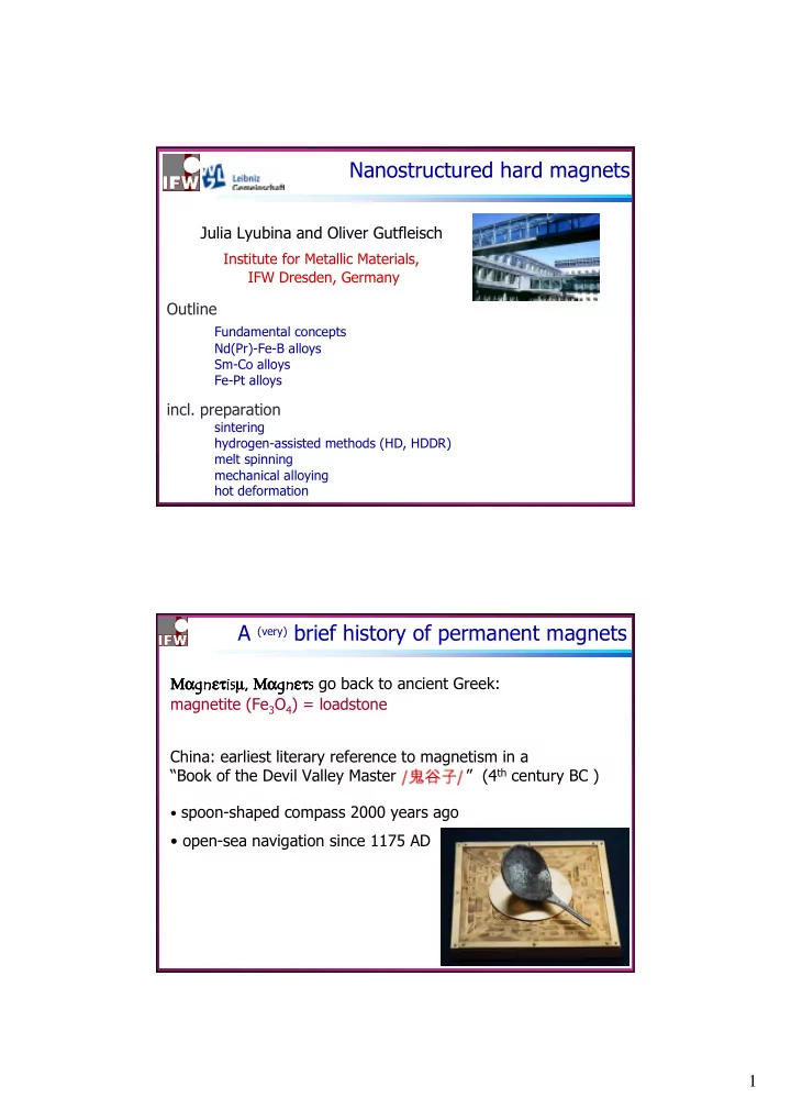
  • gobacktoancientGreek:

magnetite(Fe3O4)=loadstone China:earliestliteraryreferencetomagnetismina “BookoftheDevilValleyMaster” (4th centuryBC)

  • spoon$shapedcompass2000yearsago
  • open$seanavigationsince1175AD
slide-2
SLIDE 2

2

ThefirstplantinChinamanufacturing magneticneedlesforcompasses

A(very) briefhistoryofpermanentmagnets

Printof1637

Whatisapermanentmagnet?

J H Softmagneticmaterial

Permanentmagnet/hardmagnet – samplewithanetmagnetisation(remanenceJr)

Hardmagneticmaterial

ClassificationbasedoncoercivityHc (howeasilythematerialcanbedemagnetised)

slide-3
SLIDE 3

3

Whypermanentmagnets?

TheWalkmancirca1905

  • Strongfieldsinsmallvolumes
  • Compact
  • Nopower
  • Nocooling

Materialsforhighperformancemagnets:

Nd$Fe$B(roomtemperatureapplications) Sm$Co(hightemp.upto≈ 350°C) brittle lowcorrosionresistance

slide-4
SLIDE 4

4

Year

Progressintheenergyproduct

Fe3O4

ferrite

Nd$Fe$B

Intrinsicmagneticproperties

   

highest(BH)max

0.47 0.3 720 BaFe12O19 1.20 0.04 1133 AlNiCo

1.43 6.6 750

L10 FePt

2.16 0.05 1043

α$Fe

1.05 17 993

SmCo5

1.60 4.9 585

Nd2Fe14B

µ0MS(T) K1(MJm$3) TC(K) highestoperatingtemp. highcorrosionresistance, mechanicalstrength hightemperaturestability, highcorrosionresistance lowcost(!), goodchem.stability, electricalresistance

slide-5
SLIDE 5

5

saturationpolarisation anisotropyfield Curietemperature

intrinsic properties microstructure

100 µm > D > 1 nm

+

remanence coercivity energydensity

extrinsic properties

=

J or B Jr or Br Hc Hc

Extrinsicmagneticproperties

6 214 Dc ~ µ0 (A/K1)1/2 /Js

2

30 3.9 δw = (A/K1)1/2 α-Fe Nd2Fe14B Critical length (nm)

Dc: critical single-domain particle size δ δ δ δw δ δ δ δw: domain wall width

Critical lengths /definition nanocrystalline?

Forsphericalparticleswithuniaxial anisotropy,thecriticalsingle$domain diameter

2 s 1 c

72 M AK D µ =

2 s ex

M A l µ =

1 w

/K A = δ

Thecompetitionbetweenexchangeand magnetostaticenergy$ exchangelength (determinesthegrainsizebelowwhichthe hysteresisloopsofmulti$phasemagnetsshowa single$magnetic$phasebehaviour) Thecomparisonbetweenexchangeandanisotropy $ wall$widthparameter

[Kittel 1949]

slide-6
SLIDE 6

6

PROCESSING sintering melt$spinning mechanicalalloying/milling HDDR (hot)deformation PHASECHARACTERISATION structureidentification quantification (micro$)chemistry metastability transformation crystallographic relationships

Understandingandoptimisingproperties

NON$MAGNETICPROPs grainsize(Kmornm) texture hotworkability temperaturestability chemicalstability MAGNETICPROPs intrinsic↔ extrinsic coercivitymechanisms intergrain coupling magneticmicrostructure

Nd$Fe$Balloys

Phasediagram andcrystal structure Sinteredmagnets Anisotropicbondedmagnets(HDDR) Hotdeformedmagnets

slide-7
SLIDE 7

7

Nd Fe B

Nd2Fe14Bphase

Crystalstructure

Spacegroup:P42/mnm 68atomsperunitcell a=8.8Ǻ;c=12.2 Ǻ c$axis→ easymagnetisation axis

Nd$Fe$Bphasediagram(verticalsections)

[Landgraf 1990] [Schneider1986]

Φ=Nd2Fe14B η=Nd1.1Fe4B4

1180°C

Above685°C→ liquidphase Nd2Fe14B:verynarrowhomogeneityrange Adeparturefromthestoichiometry ⇒ foreignphases

slide-8
SLIDE 8

8

:exchangedcoupledgrainsbasedon stoichiometricR2Fe14B : exchangedcoupledgrainsbasedon nanocompositeR2Fe14B/α$Fe : decoupledR2Fe14B grainsseparated bythinparamagneticlayer

Jr Hc

  • 4
  • 3
  • 2
  • 1

1 2 3 4

  • 1,5
  • 1,0
  • 0,5

0,0 0,5 1,0 1,5

Polarisation J ( T )

single-phase exchange-coupled R-rich decoupled two-phase exchange-coupled

Applied field µ0H ( T ) Type I Type II Type III

PrototypesofR2Fe14B$basedmagnets Principalprocessingroutes

Magnetically highly anisotropic R-T-phases Coarse-grained powders

produced via hydrogen decrepitation + milling

Alignment

in magnetic field

Densification

by liquid phase sintering

Isotropic fine-grained powders (JR=JS/2)

produced by: rapid quenching mechanical alloying intensive/reactive milling HDDR

Hot compaction

isotropic, fully dense

Hot deformation

axially/radially textured

Remanence enhancement

isotropic exchange-coupled

  • ne- or multi-phase structures

„Anisotropic“ HDDR

(textured bonded magnets after pre-alignment)

NdFeB

highest (BH)max

SmCo

high operat. temp.

JR > JS/2

O.Gutfleisch,J.Phys.D:Appl.Phys. (2000)R157.

Highest (BH)max magnets

slide-9
SLIDE 9

9

adapted from Vacuumschmelze GmbH

Sintering

T

t

Vacuum-Melting Casting Crushing Milling Aligning Magnetising Machining/ Surfacetreatment Pressing

isostatic P P P P

H H

Sintering/Annealing

die$press

5$60

m particles

H~10kOe T≈ 1000

✁C

SinteredNd$Fe$Bmagnet

  • 5µm
  • Averagegrainsize~5mm

Verythincoatingof2$14$1grains withNd$richintergranular phase

10 µm 1 µm (Φ) η

  • 5µm
  • (BH)max= 451 kJ/m3

200 nm

Nd$richintergranular phase real ideal

SEM (BSE mode)

slide-10
SLIDE 10

10

  • 4
  • 2

2 4

  • 1,5
  • 1,0
  • 0,5

0,0 0,5 1,0 1,5

polarisation J (T) applied field µ0H (T) VACODYM 722HR

(BH)max=53MGOe

SinteredNd$Fe$Bmagnet

c-axis ⊥ ⊥ ⊥ ⊥ image plane c-axis II image plane

10 µm

BSEimage Orientationmappingandtexturecomponent

10 µm

Misorientation angle [deg.] Misorientation angle [deg.]

10 µm 10 µm

Kerrimage

Microtexture anddomainstructureofanisotropicmagnet

slide-11
SLIDE 11

11

Misorientation angle [deg.]

Orientationmappingandtexturecomponent Backscatteredelectronimage Kerrimage

10 µm 10 µm

Microtexture anddomainstructureofisotropicmagnet

<001> Y0 X0 {100} {111}

Anisotropicmagnetwith (BH)max =56.7MGOe Isotropicmagnet Vacodym 722 commercialgrademagnet Br=1.52T Br=1.47T Br=0.78T

5 10 15 20 25 30

J.AlloysandComp.365(2004)259

{001} {100} {111}

Textureevaluation:sinteredNdFeB

slide-12
SLIDE 12

12

adapted from Vacuumschmelze GmbH

Sintering

T

t

Vacuum-Melting Casting Crushing Milling Aligning Magnetising Machining/ Surfacetreatment Pressing

isostatic P P P P

H H

Sintering/Annealing

die$press

5$60

✂m particles

byhydrogendecrepitation

Crushing

Hydrogendecrepitation (HD)process

Decrepitation → self$pulverisationoflargemetal particlesintopowder

slide-13
SLIDE 13

13

Hydrogen decrepitated anisotropic and isotropic sintered NdFeB magnets Beneficial effect ofHDprocess onfeed rateinajet mill comparing conventional andhydrided powder

Crystallographic orientation Intergranular failure (A) (I)

2 4 6 8 10 12 2.5 3.0 3.5 4.0 4.5 hydrided powder conventional powder grain size FSSS [µm] feed rate [kg/h]

Hydrogendecrepitation (HD)process

IncorporationofsmallamountsofH2 intoNd2Fe14B!

RnTm +H2 crystalline RnTmHx amorphous RnTmHx nRHx + mT

thermo$ dynamics kinetics hydrogen pressure temperature intensity of mechanical activation

I II III

IInterstitial absorption IIAmorphisation (HIA)* IIIDisproportionation

Yeh etal.,APL42(1983)242

PossiblereactionsofR$TcompoundswithH2

Gutfleischetal.1999

atRT elevatedT Mechanical activation

slide-14
SLIDE 14

14

e.g.R2Fe14B

Soubeyroux etal.,J.Alloys Comp.1995

H2 uptake ⇒ ⇒ ⇒ ⇒ change of e$ density, bandstructure,volume ⇓ ⇓ ⇓ ⇓ modification of

3d$3dand3d$4f exchange interactions magnetic moments anisotropy spin reorientation transition

Interstitial modification andintrinsic magnetic properties

Hydrogen absorption inNd2Fe14BandSm2Fe17

(1)Hydrideformation (atmoderatepressure andtemperature) (2)Hydrogen decrepitation (HD) (3)Hydrogenationdisproportionation desorption recombination(HDDR) Nd2Fe14B+½ xH2 ⇔ Nd2Fe14BHx ± ∆H1 Nd2Fe14B+(2±x)H2 ⇔ 2NdH2±x +12Fe+Fe2B± ∆H2 Sm2Fe17 +(2±x)H2 ⇔ 2SmH2±x+17Fe± ∆H2

*

∆ ∆ ∆ ∆ ∆ ∆ ∆ ∆! Hydrogensolutionisametastable condition Atroomtemperature,reaction(3)ispreventedbytheabsenceof sufficient kinetics

slide-15
SLIDE 15

15

(1)Hydrideformation (atmoderatepressures andtemperature) (2)Hydrogen decrepitation (HD) (3)Hydrogenationdisproportionation desorption recombination(HDDR) Nd2Fe14B+½ xH2 ⇔ ⇔ ⇔ ⇔ Nd2Fe14BHx ± ∆H1 Nd2Fe14B+(2±x)H2 ⇔ ⇔ ⇔ ⇔ 2NdH2±x +12Fe+Fe2B± ∆H2 Sm2Fe17 +(2±x)H2 ⇔ ⇔ ⇔ ⇔ 2SmH2±x+17Fe± ∆H2

*

∆ ∆ ∆ ∆ ∆ ∆ ∆ ∆! Hydrogensolutionisametastable condition Atroomtemperature,reaction(3)ispreventedbytheabsenceof sufficient kinetics

Hydrogen absorption inNd2Fe14BandSm2Fe17

HDDR reaction:

Nd2Fe14B NdHx +Fe+Fe2B Nd2Fe14B

Standard$HDDR (`HydrogenationDisproportionation Desorption Recombination´) ~800° C ~1bar

temperature time

hydrogen vacuum II III IV I

100 m µ 0.3 m µ

1 bar

MagnetichardeningusingHDDR

grainrefinementviaareversiblehydrogensorption⇒ improvedcoercivity

  • O. Gutfleisch and I.R. Harris, J. Phys. D: Appl. Phys. 29 (1996) 2255
slide-16
SLIDE 16

16

HDDR:Nd2Fe14B$basedalloys

Nd2Fe14B + α-Fe µm-size grains Starting alloy " NdH2 + α-Fe + Fe2B Disproportionated alloy (650°C,70barH2 ) Nd2Fe14B + α-Fe Grain size ~ 100 nm Recombined alloy

# Rietveld refinement

slide-17
SLIDE 17

17

  • 4
  • 2

2 4

  • 1,50
  • 1,25
  • 1,00
  • 0,75
  • 0,50
  • 0,25

0,00 0,25 0,50 0,75 1,00 1,25 1,50

polarization J (T) applied field µ0H (T)

Textureandinteractiondomainsinthe

  • ptimiseddynamic$HDDRmaterial

10µ µ µ µm

(BH)max ≈ 43 MGOe

ll ⊥ ⊥ ⊥ ⊥

Alignedd$HDDR processedpowders

400nm

0.03 MPa 0.13 MPa

Highly textured Almostisotropic

Highresolution SEM Kerr

slide-18
SLIDE 18

18

10nm $%&!' 20nm

Nd12.5FebalGa0.3Nb0.3B6.3 (0.03 MPa)

Partiallydisproportionated state(TEM)

$%&!' N d H

2

N d H

2

α$Fe/ Fe(B) α$Fe/ Fe(B) NdH2 α$Fe/Fe(B)

  • J. Magn. Magn. Mat. 290-291 part 2 (2005) 1282.

aligned Fe2B grains !

Fe2B

the002reflectionofFe2B wasusedforCDFimage

100nm TetragonalFe2Btheonlyreaction productwithuniaxial crystalsymmetry

Completelydisproportionated state

α$Fe/ Fe(B) α$Fe/ Fe(B) NdH2 NdH2

& &

slide-19
SLIDE 19

19

´Standard´ HDDR(~1barH2) doesNOT workforeveryR$T compound Sm2Fe17 Sm2Co17 α-(Fe,Co) SmH2

G x

Stabilisationby %% Highpressure(~70barH2) disproportionation Co SmH2

G x

Sm2Co17 Increase of%#

Gutfleischetal.1999

ExtremeHDDR

CanHDDRbeinfluencedbyamagn.field?

slide-20
SLIDE 20

20 D$HDDR

Degreeoftexturedependsstronglyonthehydrogenpressureduringthe differentstages Well$correlatedFe2Bgrainscouldactastheanisotropy$mediatingphase Highstabilityoftheinformationcarrierunderlowhydrogenpressures makesthed$HDDRprocessapplicablefortheindustrialproductionof anisotropicpowders

HDDRinmagneticfield

Recombinationreactionisaffectedbyexternalmagneticfields Fieldprocessingcanbeusedasanadditionaltooltotailormicrostructure

  • fhardmagneticmaterials

Summary:HDDR

Sm$Coalloys

Phasediagram Hightemperaturemagnets Coercivity Interactiondomains

slide-21
SLIDE 21

21

Principalprocessingroutes

Magnetically highly anisotropic R-T-phases Coarse-grained powders

produced via hydrogen decrepitation + milling

Alignment

in magnetic field

Densification

by liquid phase sintering

Isotropic fine-grained powders (JR=JS/2)

produced by: rapid quenching mechanical alloying intensive/reactive milling HDDR

Hot compaction

isotropic, fully dense

Hot deformation

axially/radially textured

Remanence enhancement

isotropic exchange-coupled

  • ne- or multi-phase structures

„Anisotropic“ HDDR

(textured bonded magnets after pre-alignment)

NdFeB

highest (BH)max

SmCo

high operat. temp.

JR > JS/2

Highestoperatingtemperatures

  • O. Gutfleisch, J. Phys. D: Appl. Phys. 33 (2000) R157.

Sm$Cophasediagram(Cataldo etal.1996).

Precipitationhardenedmagnets

Co Sm

slide-22
SLIDE 22

22

HEAT-TREATMENT STRUCTURE

Sintering (1210-1230 0C)

  • 2:17 H formation
  • Elements taken

into solution

  • Densification

Solution treatment (1180 –1200 0C)

  • 1:7 H formation

Quenching to RT Isothermal aging (800 – 875 0C) and slow cooling (~1.0 K/min) to 400 0C

Sm$Cosystem:structuraltransformations

400

OC*1h

slow cooling 0.7° C/min Isothermal aging at 750

OC~850 OC

for 12~24h 1100~1200

OC*4~10 h

Temperature Time

Precipation$hardened 2:17Sm2Co17magnets

A B C

Hadjipanayis et al, 1999

⊥ ⊥ ⊥ ⊥ c ll c

c-axis SmCo5 Sm2Co17 Z-phase

A: 2:17 rhombohedral phase B: 1:5 hexagonal (H) phase C: lamellar phase (R B3Nb-type)

Sm(CobalFevCuyZrx)7:typicalmicrostructure

slide-23
SLIDE 23

23

5 nm 50 nm

Cu Co Fe Sm

  • 3,0
  • 2,5
  • 2,0
  • 1,5
  • 1,0
  • 0,5

0,0 0,00 0,25 0,50 0,75 1,00 1,25

550° C 500° C 400° C 300° C 200° C 25° C

magnetisation M ( T ) field µ0H ( T )

25° C after 550° C

(BH)max = 82 kJ/m3 Jr = 0.67 T K0iHc = 0.74 T

at500 °C:

A.Handstein etal.,IEEETrans.onMagn.39(2003)2923

Sm(Co0.784Fe0.1Cu0.088Zr0.028)7.19

2:17SmCo:hightemperaturegrade

ElementmappinginTEM

  • 3
  • 2
  • 1

1

  • 0.25

0.00 0.25 0.50 0.75 1.00 25° C-start 500° C-start 500° C-20' 500° C-60' 500° C-100' 25° C-final 1st Recovery

Polarization J ( T ) Internal Field µ0Hi ( T )

Sm(Co0.738Fe0.144Cu0.088Zr0.028)7.19

  • DegradationofBr &(BH)max with

increasingtime

( RECOVERYofJHc afterrepetition

  • flastsegmentoforiginalheat

treatment⇒ ⇒ ⇒ ⇒ Changesofmicrochemistryin 1:5$typecellboundaryphase

  • 0.50
  • 0.25

0.00 0.4 0.5 0.6 TIME 500° C-start 500° C-20' 500° C-60' 500° C-100'

Polarization J ( T ) Internal Field µ0Hi ( T )

2:17SmCo:in$situmeasurementat500°C

slide-24
SLIDE 24

24

  • 4
  • 2

2 4 6 8

  • 0.8
  • 0.4

0.0 0.4 0.8

slow cooling to 400

  • C

without slow cooling

J (T)

µ0H (T)

“type II” ribbon “type I” ribbon

A.Yan etal.,Appl.Phys.Lett.80(2002)1243 A.Yanetal,IEEETrans.Magn.38(2002)2937

Sm2Co17 ribbons

Simpleprocessing: nosolidsolution treatment noisothermal aging at850°C

0.00 0.25 0.50 0.75 1.00

(a)

1:5 phase

Cu (at%)/Cu

max

0.00 0.25 0.50 0.75 1.00

(b)

2:17 phase

Cu (at%)/Cu

max

largegradientofCuwithin thecellboundaryphaseof thehighlycoerciveribbons ⇓ pinning forcemodified

850ºC/3h,quenching (low coercivity atRT)

“type I” ribbon “type II” ribbon

2 4 6 8 10

Position (nm)

  • A. Yan, O. Gutfleisch, T. Gemming, K.-H. Müller, J. Appl. Phys. 93 (2003) 7975

Sm(Co,Fe,Cu,Zr)7.5:EDXCuprofilesnearcellboundary

850ºC/3h,slow cooling to400ºC(highHc atRT)

TEM

slide-25
SLIDE 25

25

Principalprocessingroutes

Magnetically highly anisotropic R-T-phases Coarse-grained powders

produced via hydrogen decrepitation + milling

Alignment

in magnetic field

Densification

by liquid phase sintering

Isotropic fine-grained powders (JR=JS/2)

produced by: rapid quenching mechanical alloying intensive/reactive milling HDDR

Hot compaction

isotropic, fully dense

Hot deformation

axially/radially textured

Remanence enhancement

isotropic exchange-coupled

  • ne- or multi-phase structures

„Anisotropic“ HDDR

(textured bonded magnets after pre-alignment)

NdFeB

highest (BH)max

SmCo

high operat. temp.

JR > JS/2

  • O. Gutfleisch, J. Phys. D: Appl. Phys. 33 (2000) R157.

Meltspinning

Ar pressure Induction heatingcoil Melt$spun ribbon Rotatingwater$ cooledwheel (Cu,Cr…) Moltenalloy

Solidificationrateupto105$106 K/s $ wheelrotationspeedvs $ typeandpressureoftheinertgas $ crucibleopeningsize $ distancecrucible↔ wheel $ temperatureofthemelt Melt$spunNd$Fe$B Underquenched (veryslowvs) Optimallyquenched(vs ≈ 5m/s) Overquenched (vs 20m/s) > ~ Ribbons(orflakes)of30$50 Kmthickness arethrownoffthewheelsurface

slide-26
SLIDE 26

26

Kanekiyo etal.,JAP83(1998)6265.

Underquenched (veryslowvs) Multidomain Nd2Fe14B <D>= 100nm…10Km; largeα$Feinclusions Optimallyquenched (vs ≈ 5m/s) Nd2Fe14Bgrainsize<100nm +softmagneticα$FeandFe3B Overquenched (vs ≈ 20m/s) amorphous(Fe$richalloys) amorphous/nanocrystalline

Melt$spunNd$Fe$B:quenchingrate

)*+

slide-27
SLIDE 27

27

Principalprocessingroutes

Magnetically highly anisotropic R-T-phases Coarse-grained powders

produced via hydrogen decrepitation + milling

Alignment

in magnetic field

Densification

by liquid phase sintering

Isotropic fine-grained powders (JR=JS/2)

produced by: rapid quenching mechanical alloying intensive/reactive milling HDDR

Hot compaction

isotropic, fully dense

Hot deformation

axially/radially textured

Remanence enhancement

isotropic exchange-coupled

  • ne- or multi-phase structures

„Anisotropic“ HDDR

(textured bonded magnets after pre-alignment)

NdFeB

highest (BH)max

SmCo

high operat. temp.

JR > JS/2

Textured magnets by hot deformation

Anisotropictexturedmagnetsbyhotdeformation

Meltspinning Hotpressing Dieupsetting

Magnetically isotropicribbons

v vMS

MS =20

=20$ $40m/s 40m/s T=6750C, P=150MPa T=7250C

Isotropicfullydense precursor Fullydensemagnetwith c$axisalignmentalong thepressingdirection Fullydensemagnetwith radialc$axisalignment

Backwardextrusion Liquidphaseispresent!

slide-28
SLIDE 28

28

  • 2.5
  • 2.0
  • 1.5
  • 1.0
  • 0.5

0.0 0.5 1.0 1.5 µ µ µ µ0H (T)

% // ⊥ ⊥ ⊥ ⊥

J (T)

0.28 0.53 0.62 0.72 0.79 0.1

EDX line scan Counts

30 25 20 15 10 5

Fe Nd Ga

Position (nm)

Nd13.6Fe73.6Ga0.6Co6.6B5.6

200nm

TextureinfinegrainedNdFeB magnets

+# , ⊥

⊥ ⊥ ⊥-

5µm Texture histogram

{001} {100} {111}

TextureinfinegrainedNdFeB magnets

slide-29
SLIDE 29

29

Principalprocessingroutes

Magnetically highly anisotropic R-T-phases Coarse-grained powders

produced via hydrogen decrepitation + milling

Alignment

in magnetic field

Densification

by liquid phase sintering

Isotropic fine-grained powders (JR=JS/2)

produced by: rapid quenching mechanical alloying intensive/reactive milling HDDR

Hot compaction

isotropic, fully dense

Hot deformation

axially/radially textured

Remanence enhancement

isotropic exchange-coupled

  • ne- or multi-phase structures

„Anisotropic“ HDDR

(textured bonded magnets after pre-alignment)

NdFeB

highest (BH)max

SmCo

high operat. temp.

JR > JS/2

  • O. Gutfleisch, J. Phys. D: Appl. Phys. 33 (2000) R157.

Isotropic remanence-enhanced magnets

Fe$Ptalloys

Phasediagram andcrystal structures Magnetism ofFe$Pt Phaseformation innanocrystalline Fe$Ptalloys Structure andmagnetic properties Magnetisation reversal processes Magnetic moments ofordered andpartially ordered Fe$Pt → APL89(2006)032506

slide-30
SLIDE 30

30

Applications:thinfilms/nanoparticles

(Micro-drive IBM 1Go)

Datastorage

Needs: monodisperse FePt particlesabout 4nminsizeself$assembledinperiodic arraysoveranextendedarea

FePt self$organisingmedia 130nm

Seagate Technology

Challenges:obtainingL10 structurewithout undesiredagglomeration,coalescenceofthe particlesandlossofperiodicity

Formagnetic recordingsee L.Ranno (Sunday)

MEMS(magneticMEMS)

permanentmagnets

Dyna Dental Engineering bv, The Netherlands Aichi Steel, Japan

Motors,actuators,sensors, telecommunicaition,robotics…

Medicalapplication

Applications:thickfilms/bulk

permanent magnet substrate dielectric switchingcoil Fe$Nicantilever supports RFtransmission linewithgap magnet

slide-31
SLIDE 31

31

Fe$Ptphase diagram

Pt Fe

a b c x y z

L10 (P4/mmm)

a b c x y z

A1 (Fm3m)

a b c x y z

L12 (Pm3m) L12

  • $ Strong exchange interaction I

$ Largedensity ofstates N(EF)

Stoner criterion:I·N(EF) > 1

  • /

2 ) (

z B B s

S n n µ µ µ − = − =

↓ ↑

Spinmoment: FePt – itinerant ferromagnet

Magnetic moments

I = ∆E/µs

Spontaneouslyspin$splitbands

slide-32
SLIDE 32

32

enhanced Femoment ≈ 2.8µB inducedmomentonPtsites≈ 0.4µB

5d(Pt)$3d(Fe)hybridisation inFePt ⇒ µl (symmetry +ξ)

µ µ µ µtot (FePt) = µ µ µ µs + µ µ µ µl ≈ ≈ ≈ ≈ µ µ µ µs

Magnetic moments

Stoner criterion: I·N(EF) > 1

) ( 1 ) ( 2

2 B F F

E N I E N ⋅ − = µ µ χ

exchange$enhanced paramagnet

0.5$0.7 0.6 Pt 1.5$1.7 0.07 2.27 0.04 2.23 α$Fe

µtot µl µs

I—N(EF)

SOcoupling

ξ,eV

Magneticmoment,µB Pauliparamagnet

1.0 1.2 1.4 1.6

  • 4
  • 3
  • 2
  • 1

1

∆E [meV/f.u.]

c

*/a * ratio

exper.

Magnetocrystalline anisotropy (MCA)

SO interaction couples the isotropic µs to the crystal lattice ⇒ MCA MCA in L10 FePt ⇒ large SO coupling (ξ) in Pt + 5d(Pt)-3d(Fe) hybridisation

Lyubinaetal.,J.Phys.:Cond.Matter.17(2005)4157

Fe Pt

slide-33
SLIDE 33

33

Magnetic properties ofthe Fe$Ptphases

Room temperature

Aim:Exchangecoupled FePt/Fe3Ptnanocomposite

Hard/softnanocomposites

Exchange$coupling effective if

  • grain size <D>sufficiently small (~δw

soft)

  • phases suitably distributed

softmagnetic phase (α$Fe, Fe3Pt...)

↑ ↑ ↑ ↑

hard magnetic phase (Nd2Fe14B,L10 FePt...)

↑ ↑ ↑ ↑

Intrinsic magn.properties /Ms,Tc,Ha/:interaction onthe atomic scale Extrinsic magn.properties /Mr, Hc,(BH)max/:interplay structure ↔ intrinsic properties

slide-34
SLIDE 34

34

slide-35
SLIDE 35

35

Fe50Pt50(isothermal heat treatment)

  • Microstructure preserves alamellar character even after annealing
  • The crystallites within the lamellae are substantially smaller

than the lamellae thickness 2hmilled +450°C/48h

Lyubinaetal.,Scripta Materialia 53(2005)469.

slide-36
SLIDE 36

36

  • As$milled powders → softmagnetic behaviour
  • Ashoulder inthedemagnetisation curves due tounreacted α$Fe

(samples annealedfor 10min and1h)

  • Optimummagnetic properties inFe50Pt50 for 450°C/48h

Fe50Pt50:magnetic properties

  • 1.0
  • 0.8
  • 0.6
  • 0.4
  • 0.2

0.0 0.0 0.2 0.4 0.6 0.8

48 h 16 h 1 h 10 min as-milled

Polarisation J (T) Internal field µ0H (T)

Milling +450°C

Lyubinaetal.,JAP95(2004) 7474.

Fe100$xPtx:effect ofcomposition

20 40 60 80 100

FePt3 Fe3Pt FePt (A1) FePt (L10) Phase amount (vol. %)

40 45 50 55 60 0.0 0.5 1.0 1.5 2.0

J16 Jr µ0Hc µ0Hc , Jr , J16 (T) Pt concentration x

450 °C, 48 h

Heat treatment ⇒ wellordered L10 FePt (S=0.91– 0.98) + L12(Fe3Ptor FePt3) Hc increaseswithx uptox=50 → duetoL10 fractionincrease, concurrentwithFe3Ptamountreduction forx>50 → FePt3 (paramagnetic atRT) decouplesthegrainswithin thelamellaeof L10 FePt

Lyubinaetal.,JMMM290$291(2005)547.

slide-37
SLIDE 37

37

  • 1.5
  • 1.0
  • 0.5

0.0

  • 1.2
  • 0.8
  • 0.4

0.0 0.4 0.8 1.2

  • 1.0
  • 0.5

0.0

  • 1.0
  • 0.5

0.0

Fe60Pt40

Polarisation J (T) Field µ0H (T)

Fe55Pt45

Field µ0H (T)

Fe50Pt50

Field µ0H (T)

Fe100$xPtx:exchange coupling

  • Fe$rich alloys: fairly highrecoil permeability

shoulder inthe demagnetisation curves

  • Weaklypronouncedexchange$spring behaviour

two$phase demagnetisation behaviour

JMMM290$291(2005)547.

Grainsize* ofthe phases is small enoughforexchange$spring behaviourtobepresent: FePt(L10):<D>≈ 30nm Fe3Pt: <D>=18$25nm OnlyalimitedamountoftheFe3Ptgrains,thegrainsattheboundaryofthe L10 phase,canparticipateinexchange$coupling

Fe100$xPtx:exchange coupling

* Obtained from the xrd line broadening after separation of size and strain effects

slide-38
SLIDE 38

38

  • 1.00
  • 0.75
  • 0.50
  • 0.25

0.00 0.0 0.2 0.4 0.6 0.8 1.0 1.2 Polarisation J (T) Field µ0H (T)

Exchange-spring behaviour

Exchange$spring FePt/Fe3Pt

Fe60Pt40 (BH)max = 104 kJ/m3 Fe55Pt45 (BH)max = 121 kJ/m3 Fe50Pt50 (BH)max = 104 kJ/m3

Nanoscale multilayer$type distribution of chemically highly ordered L10FePt andFe3Pt

  • 1.00
  • 0.75
  • 0.50
  • 0.25

0.00 0.0 0.2 0.4 0.6 0.8 1.0 1.2

Fe55Pt45 Fe60Pt40 Fe50Pt50

Polarisation J (T) Field µ0H (T)

Fe55Pt45 (4hmilled +450°C/48h)

Lyubinaetal.,J.Phys.:Cond.Matter.17(2005)4157

  • Developmentandtexturingofnewnanocomposite systems
  • Developmentofnewnon$equilibriumprocessingroutesaswellas

texturingtechniques

  • Materialsdevelopmentrequiresalladvancedcharacterisation

techniquesfromelectronmicroscopies,atomprobe,synchrotron$based spectro–microscopies,neutronscattering,highresolutionmagnetic imagingtolarge$scalecomputationalsimulations

Projections:permanentmagnets

slide-39
SLIDE 39

39

  • Phasediagramsimulation
  • fquaternary,… systems
  • Combinatorialtechniques

usingmaterialspreads magnetisationbehaviour homogeneityofmag.prop. chemicalstability thermalstability machineability netshape$processing geometry cost Magneticandnon$ magnetic figuresofmerit

Projections:furtherprogressin(BH)max

‘Extreme‘ die$upset sheet shaped magnets

200 µm thick 360 µm thick

Projections:magneticMEMS

D.Hinzetal.,18th WorkshoponHighPerformanceMagnets&theirApplications,2004,p.797.

slide-40
SLIDE 40

40 Demagnetisation curves

ϕ - strain, h - final thickness, ϕ - strain rate, t – duration of die-upsetting

  • 1.6
  • 1.2
  • 0.8
  • 0.4

0.0 0.0 0.4 0.8 1.2 ϕ h ϕ t [µm] [10

  • 3/s] [min]

1.0 360 2 8 1.1 300 3.3 9 1.9 600 2 17 1.9 450 3.3 12 1.8 500 1 39

Polarization J [ T ] Magnetic field µ0H [ T ]

Tdef = 750 ° C

Projections:magneticMEMS

Surface flux density distribution

1 2 3 4 5 6 50 100 150 200 distance from the surface 0 mm 0.15 mm 0.30 mm with without Fe core

Flux density [ mT ] Position [ mm ]

3D representation Line scan

430 µm

Projections:magneticMEMS

D.Hinzetal.,18th WorkshoponHighPerformanceMagnets&theirApplications,2004,p.797.

slide-41
SLIDE 41

41

Projections:magnetocaloric materials

Magneticrefrigerationcycle

Magnetocaloriceffect(MCE) → emissionorabsorptionof heatinamagneticmaterialin responsetoachanging magneticfield.