
SLIDE 1
- NAEAANALZE
TyZE
M
5
whj
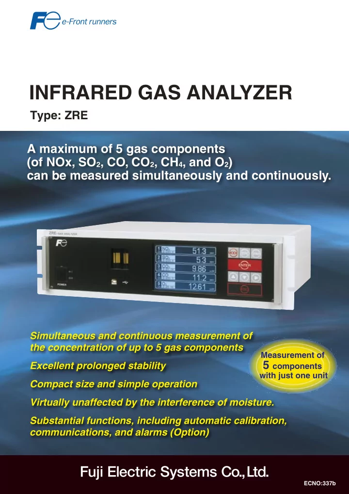
Ax5 (NOx,O2,CO,CO2,CH4,O2) byy
ECNO337b
NAEAANALZE (NOx,O 2 ,CO,CO 2 ,CH 4 - - PDF document
M
whj
ECNO337b
2
Ey-wLC InstructioninEngrishfacilitatesoperation. hhLightweight(approximately8kg) y N
Zby
Usedformanualzero calibration.
Mwh
Usedtoswitchmodes.
by
Usedformanualspan calibration
Ey
Usedtoconfirmthe selecteditemsand numericvalues.
Uwy
Usedtoswitchtheitems tobeselected.
Ey
Usedtoreturntothe previousscreenorabort settingmidway.
TypeZR TypeZRE
M
OFFfunction) Powerswitch Samplegasflowmeter USBconnector(TypeB)for RS-485(Modbus) communications 19"rackmountstructure Panel-mountanddesktoptypesare alsoavailable.
Externalanaloginput connector RS-485communication connector Purgegasinlet (Rc1/4orNPT1/4) DigitalI/Oconnector Samplegasinlet (Rc1/4orNPT1/4) Samplegasoutlet (Rc1/4orNPT1/4) Analogoutput connector 0mm
A
y A
132.5mm Fuse Note) Samplegas inlet2Rc1/4orNPT1/4 Note) Samplegas
Note) Usedforspecialcase. Powersupply/grounding terminalM3.5 (100to240VAC,50/60Hz)
3
Exby,y, hh-wh by05% Vybyh
hhLightweight(approximately8kg) AbO(Option)
Zb() bw
Analysis is almost unaffected by any moisture present in the sample gas. Our unique interference correcting function has significantly reduced the effect of moisture.
CH4 O2 NO H2Osaturation at20˚C 1%orlower 1%orlower 1%orlower -
at2˚C
lower
lower CO1000ppm 1%orlower - 1%orlower 1%orlower 1%or lower CO215%
lower CH41000ppm 1%orlower 1%orlower - 50ppmor lower
Mass flow sensor Infrared ray light source Motor Measuring cell Chopper Gas outlet Gas inlet
(ΔP) sensitivity Whenwind blowsfrom theleft Detection (ΔP) sensitivity Whenwind blowsfrom theright Perfectcalm
H-w
Mw
Themassflowsensor,withlow impedance,hasexcellentnoiseresistance, whilethesensor,withnomovableparts,is impervioustovibrationandcanbeused
Theamountofinfraredrayabsorbedinthemeasuringcellis detectedwiththemassflowsensor. Massflowsensor (Hot-wiresensor)
1mm□ RS-485(Modbus)communication WiththeUSBconnector(gageonthefrontface), RS485connectorforcommunicationontherearface
w,
Flowmeter Membranefilter
Calibrationisperformedatpreviously designatedintervals Calibrationintervals: 1to99hoursor1to40days
Standardgasfor zerocalibration Standardgasfor spancalibration Autocalibration start/stopsignal Solenoid valve
Rangeswitching,autocalibrationstart,
Ex
Identificationofeachcomponentrange, instrumentfailure,calibrationerror,auto calibrationinprogress,upper/lowerlimit alarmforeachcomponent,pumpON/OFF, solenoidvalvedriveforautocalibration
(y)
Theconcentrationoffivegascomponents(ofSO2,NOx,CO,CO2,CH4,andO2) canbemeasured.Forexample,thecomponentsinflueexhaustgas(SO2,NOx, CO,CO2,andO2)canbemeasuredsimultaneouslyandcontinuously.
NO SO₂ CO CO₂ CH₄ O₂
yz
○ ○ ○ ○ ○
Canbeaddedby designation b- yz
○ ○ ○ ○ ○ ○ ○ ○ ○ ○
Canbeaddedby designation Th- yz
○ ○ ○ ○ ○ ○
Canbeaddedby designation
yz
○ ○ ○ ○
Canbeaddedby designation
M
NO: 0-200ppm........................ 5000ppm SO2: 0-200ppm.............................10% CO2: 0-100ppm...........................100% CO: 0-200ppm...........................100% CH4: 0-500ppm ...........................100% O2: 0-5% .....................................25%
Mh5yy
CwhChwh485 (Mb)(O)
4
Exxhb (NO,O2,CO,CO2,O2) ExCO,CH4,CO2
NO2→NO(TyZLO4) Zxy(TyZK7) (TyZAK2)
Ey xb300°C
(TyZC9)
E
Targetgas:Exhaustgasfromgeneral boilers,atmosphere
Catalystusage:2cm
3
Catalystreplacementinterval: Approximately1year
Flowrateofthegastobeanalyzed:0.5 L/minorlower
Conversionefficiency:90%orhigher (conformingtoIS)
Powersupplyvoltage:100to240VAC, 50/60Hz
Externaldimensions: 212(H)x148(W)x130(D)mm
Responsetime:Approximately20sec (90%response)
Oxygenconcentrationdisplay: Displayedonthegasanalyzer connected
Flowrateofthegasmeasured:0.5±0.25 L/min
Maximumtemperatureofthegasused: 800°Cor1300°C
Materialofthegas-contactingarea: SUS316,Viton
Powersupplyvoltage:100VAC,50/60Hz, 100VA
Fixeddehumidificationflowrate(Max.):1.5 L/min
Dehumidificationcheckfunction:With checkterminal
Externaldimensions: 250(H)x200(W)x16(D)mm
4-way switch cock Membrane filter Gas aspirator Drain pot Drain pot Ball valve Sample gas
Primaryfilter
Electronic gas cooler Standard gas for zero calibration Standard gas for span calibration Gas outlet ZRE unit CO, CO2, CH4
O2 Gas extractor Gas aspirator Mist filter Safety drain trap Gas outlet Drain Electronic gas cooler Membrane filter NO2/NOconverter (forNOxmeasurement) Pressurereducingvalve Solenoidvalve Standard gas ZERO NO SO2 CO2 CO O2 Zirconia O2 sensor (ZFK7)
ZRE unit NO,SO2, CO2, CO
5
Cb x
signal Contactsignal
ZREtype
CO2
Gasextractor Gassamplingequipment MNO,O2,CO,CO2,O2
ZREtype
Ah
b
CH4,CO2O2yzb-
CO2O2yzhb
bhbyhCO2O2y h
Exxhb (NO,O2,CO,CO2,O2)
Ax5(NOx,O2,CO,CO2,O2)b yy
Mh
CH4,CO2,O2yz
ZREtype ZREtype
z
Alternativecurrent
6
Digit
Description
Note
Code 4 Standard A 5 <Installationstructure> 19”rackmounttype,ConformingtoEIS B 19”rackmounttype,ConformingtoIS C Panelmounttype D 6 <Measurablecomponents(NO,SO2,CO,CH4)> 1st 2nd 3rd 4th
Note1
None Y NO P SO2 A CO2 D CO B CH4 E NO SO2 F NO CO G CO2 CO
CO K CO2 CH4 L NO SO2 CO N CO2 CO CH4 T NO SO2 CO2 CO V Others Z <Measurablecomponent(O2)> None Y ExternalO2sensor(0to1VDC)
Note2
1 ExternalzirconiaO2sensor(TypeZFK) 2 Built-infuelcellO2sensor 3 Built-inparamagneticO2sensor 4 9 <1stcomponent,1stmeasurementrange>
Note3
SeeTable1. □ 10 <1stcomponent,2ndmeasurementrange>
Note3
SeeTable1. □ 11 <2rdcomponent,1stmeasurementrange>
Note3
SeeTable1. □ 12 <2rdcomponent,2ndmeasurementrange>
Note3
SeeTable1. □ 13 <3rdcomponent,1stmeasurementrange>
Note3
SeeTable1. □ 14 <3rdcomponent,2ndmeasurementrange>
Note3
SeeTable1. □ 15 <4thcomponent,1stmeasurementrange>
Note3
SeeTable1. □ 16 <4thcomponent,2ndmeasurementrange>
Note3
SeeTable1. □ 1 <Measurablerange(O2sensor)> None Y 0to5/10% A 0to5/25% B 0to10/25% C 0to5% L 0to10% M 0to25% V 0to50% P 0to100% R Others Z 18 <Gasoutlet/inletconnection> Rc1/4 1 NPT1/4 2 19 <Outputsignal> 0to1VDC A 4to20mADC B 0to1VDCRS485communicationfunction C
4to20mADCRS485communicationfunction
D
Digit
Description
Note
Code 20 <Display> apanese
E Chinese C 21 <O2collectionandO2averagevalueoutput>
Note4
None Y WithO2correctionoutput A
WithO2correctionoutput,O2correctionandaverageoutput
C 22 <Optionalfunction(DI,DO)> FAULT Auto calibration
Upper/lower limitalarm
Rangeidenti- fication/Remote
None Y ○ A ○ ○ B ○ ○ C ○ ○ D ○ ○ ○ E ○ ○ ○ F ○ ○ ○ G ○ ○ ○ ○
Note5
H 24 <Unit> ppm,% A mg/m3,g/m3
Note6
B 25 <Adjustment>
Note
Standard A Forheattreatmentfurnace C Forconverter D Others Z
Tb
<Measurementrange codetable>
Measurementrange
Code 0to100ppm B 0to200ppm C 0to250ppm D 0to300ppm S 0to500ppm E 0to1000ppm F 0to2000ppm G 0to2500ppm U 0to3000ppm T 0to5000ppm H 0to1%
K 0to3% Q 0to5% L 0to10% M 0to20% N 0to25% V 0to40% W 0to50% P 0to0% X 0to100% R Others Z
4 5 6
9 10 11 12 13 14 15 16 1 18 19 20 21 22 23 24 25
ZE
A 1 − − − Y
Note1: Specifycode“Y”whentheO2sensoronlyisrequired.WhenNO,SO2measurmentis specified[Autocalibration]mustbespecified22thdigit. Note2: FeedinputsignalsfromtheexternalO2sensorlinearlywithintherange0to1VDCagainst thefullscale.OurexclusivezirconiaO2sensor(ZFK)andexternaloxygensensorare alsooptionallyavailable. Note3: Selectthemeasurablecomponentandrangefromthetableonpages.Ifcode“Y”is selectedforthe6thdigit,specify“Y”forallofthedigitsfromthe9thto16th. Note4: O2correctionoutputandO2correctionaverageoutputaremadeforNO,SO2,andCOonly. Note5: Notapplicabletothe5-componentsensor.Thenumberofoutputpointsforupper/lower limitalarmsis3forthe4-componentsensor. Note6: Evenifcode“B”isspecified,selectthemeasurementrangeinunitofppm.Avalue convertedintothemg/m
3rangewillbedelivered.ApplicableonlytoNO,SO2,andCO
sensors.Seethefollowingtableforcorrespondencebetweenppmandmg/m
3.
Note: Adjustmentwillbemadeusingthefollowingbalancegasforallthecodesfrom“A”to “D”beforedelivery.Specify“Z”ifadjustmentwithothergasesisdesired.Standard“A”: BalancegasN2,“C”forheattreatfurnace:Balancegas30%H2/0%N2,“D”forconverter: BalancegasCO,CO2 Attachatablethatliststhecomponentscontainedinthegastobemeasuredif“Others”is specified. Ifmg/m
3isselected,specifytheminimumtomaximumrangeinppmthatcorrespondstoyour
desiredrangeexpressedinmg/m
3.Deliverywillbemadewithadjustmentmadetosatisfythe
correspondingmg/m
3range.
Theconversionformula"ppm"unitinto"mg/m
3"unit.
NO(mg/m
3)=1.34×NO(ppm)
SO2(mg/m
3)=2.86×SO2(ppm)
CO(mg/m
3)=1.25×CO(ppm)
Correspondingrangeexpressedinmg/m
3
Rangecode Unit:ppm NO SO2 CO C 0to200ppm 0to260mg/m
3
0to50mg/m
3
0to250mg/m
3
D 0to250ppm 0to325mg/m
3
0to00mg/m
3
0to300mg/m
3
S 0to300ppm 0to400mg/m
3
0to850mg/m
3
0to35mg/m
3
E 0to500ppm 0to650mg/m
3
0to1400mg/m
3
0to600mg/m
3
F 0to1000ppm 0to1300mg/m
3
0to2800mg/m
3
0to1250mg/m
3
G 0to2000ppm 0to2600mg/m
3
0to5600mg/m
3
0to2500mg/m
3
U 0to2500ppm 0to3300mg/m
3
0to100mg/m
3
0to3000mg/m
3
T 0to3000ppm 0to4000mg/m
3
0to8500mg/m
3
0to350mg/m
3
H 0to5000ppm 0to6600mg/m
3
0to14.00g/m
3
0to6250mg/m
3
7
Mb
2 Minimumrange Maximumrange Minimumrange Maximumrange NO 0to200ppm 0to5000ppm 0to250ppm 0to5000ppm O2 0to200ppm 0to10% 0to250ppm 0to10% CO 0to200ppm 0to100% 0to250ppm 0to100% CO2 0to100ppm 0to100% 0to200ppm 0to100% CH4 0to500ppm 0to100% 0to1000ppm 0to100%
bbhhhhfih 0 ,fi(E3-33)
NO+O2
Mb
2 Minimumrange Maximumrange Minimumrange Maximumrange NO 0to200ppm 0to5000ppm 0to250ppm 0to5000ppm O2 0to200ppm 0to5000ppm 0to250ppm 0to5000ppm
NO+CO
Mb
2 Minimumrange Maximumrange Minimumrange Maximumrange NO 0to200ppm 0to5000ppm 0to250ppm 0to5000ppm CO 0to200ppm 0to5000ppm 0to250ppm 0to5000ppm
CO2+CO
Mb
2 Minimumrange Maximumrange Minimumrange Maximumrange CO2 0to100ppm 0to100% 0to200ppm 0to100% CO 0to200ppm 0to100% 0to250ppm 0to100%
CH4+CO
Mb
2 Minimumrange Maximumrange Minimumrange Maximumrange CH4 0to500ppm 0to100% 0to1000ppm 0to100% CO 0to200ppm 0to100% 0to250ppm 0to100%
CO2+CH4
Mb
2 Minimumrange Maximumrange Minimumrange Maximumrange CO2 0to100ppm 0to100% 0to200ppm 0to100% CH4 0to500ppm 0to100% 0to1000ppm 0to100%
2-yz
NO+O2+CO
Mb
2 Minimumrange Maximumrange Minimumrange Maximumrange NO 0to200ppm 0to5000ppm 0to250ppm 0to5000ppm O2 0to200ppm 0to5000ppm 0to250ppm 0to5000ppm CO 0to200ppm 0to5000ppm 0to250ppm 0to5000ppm
CO2+CO+CH4
Mb
2 Minimumrange Maximumrange Minimumrange Maximumrange CO2 0to5000ppm 0to100% 0to1% 0to100% CO 0to500ppm 0to100% 0to1000ppm 0to100% CH4 0to5000ppm 0to100% 0to1% 0to100%
3-yz
NO+O2+CO2+CO
Mb
2 Minimumrange Maximumrange Minimumrange Maximumrange NO 0to200ppm 0to5000ppm 0to250ppm 0to5000ppm O2 0to200ppm 0to5000ppm 0to250ppm 0to5000ppm CO2 0to1% 0to50% 0to2% 0to50% CO 0to200ppm 0to2500ppm 0to250ppm 0to2500ppm
4-yz
8
Printedinapan2008-12/15FIS
GateCityOhsaki,EastTower,11-2,Osaki1-chome, Shinagawa-ku,Tokyo141-0032,apan http://www.fesys.co.jp/eng Phone:81-3-5435-280,281Fax:81-3-5435-425 http://www.fic-net.jp/eng Informationinthiscatalogissubjecttochangewithoutnotice.
Measurement principle NO,SO2,CO,CO2,CH4:Non-dispersiveinfrared rayabsorption(Single-beamsystem) O2:Fuelcell(builtin)orzirconia(externallyinstalledZFK byFuji)orParamagnetic(builtin) Measurable componentand range
Measuredcomponent
Minimumrange Maximumrange NO 0-200ppm 0-5000ppm SO2 0-200ppm 0-10vol% CO2 0-100ppm 0-100vol% CO 0-200ppm 0-100vol% CH4 0-500ppm 0-100vol% O2 0-10vol% 0-25vol% Fuelcell(builtin) O2 Zirconia 0-5vol% 0-25vol%
ParamagneticO2sensor
Switchingbetween2rangesallowedforeachcomponent. Maximumrangeratio: 1:10(excludingO2) Repeatability ±0.5% FS Linearity ±1.0% FS Zerodrift Within±2%FS/week Spandrift Within±2%FS/week Responsetime Within60sec(90%responsefromgasinlet) Variesdependingonthecomponentstobemeasuredand themeasurementrange. Analog
4to20mAor0to1VDC(12pointsatmax.) Instantaneousvalueoutput (Concentrationofeachgascomponentmeasured) Option:O2correctioninstantaneousvalueoutput, O2correctionaverageoutput,O2averageoutput Display LCDwithbacklight(apanese,Englishorchinesebydesignation) Instantaneousvalueofeachcomponent,O2correction instantaneousvalue. O2correctionaverage,O2average,parametersetting,with autoOFFfunction Rangeswitching Manualswitchingbykeyoperation,autoswitching,external contactinputswitching(option) Externaldigital input(option) Voltagecontact(supply12to24VDC/15mAmax.atON) 9pointsatmax. Rangeswitching,autocalibrationstart,outputsignalhold, averagevaluereset
483 443 Externalinputconnector(A/I) Connectorforcommunication(RS485) Connectorforanalogoutput(A/O) ConnectorfordigitalI/O PurgegasinletRc1/4orNPT1/4 SamplegasinletRc1/4orNPT1/4 Note1)Samplegasinlet2Rc1/4orNPT1/4 Note1)Usedforspecialcase. SamplegasoutletRc1/4orNPT1/4 Note1)Samplegasoutlet2Rc1/4orNPT1/4 LengthA IS:50mm EIA:5.2mm Powerterminal 435 436
2
124.5 A 21 39
2
Contactoutput function(option) 1crelaycontact(15pointsatmax.) Identificationofeachcomponentrange,instrument failure,calibrationerror,autocalibrationinprogress,upper/ lowerlimitalarmforeachcomponent,solenoidvalvedrive forautocalibration Communication function(option) RS-485(MODBUSprotocol) Detailsofcommunication:Read/writeofeachsetting,
Type-BwithUSBconnector(frontface)andUSBdriver Samplegas flowmeter Builtin Gasoutlet/inlet dimension Rc1/4orNPT1/4 Purgegasflowrate 1L/min(Performedasrequired.) Structure Indoortypewithsteelcase Ambient temperature/ humidity −5°Cto45°C,90RHorlower(Nocondensationallowed.) Mountingmethod 19”rackmount,panelmount,desktop Powersupply voltage 100to240VAC,50/60Hz,100VA Outsidedimension 133×483×418mm(19”rackmount) 133×440×418mm(Panelmount) Mass Approximately8kg(5-componentanalyzer) Applicable standard CEmark <Measuredgasconditions> Flowrate 0.5L/min±0.2L/min Temperature 0°Cto50°C Pressure 10kPaorlower Dust 100µg/Nm3orlower(Particlesize:0.3µmorsmaller) Mist Notallowed. Moisture Saturationatroomtemperatureorlower (Nocondensationallowed.) Saturationat2°Corlower(Nocondensationallowed.) Corrosive component HCl:1ppmorless