
SLIDE 1
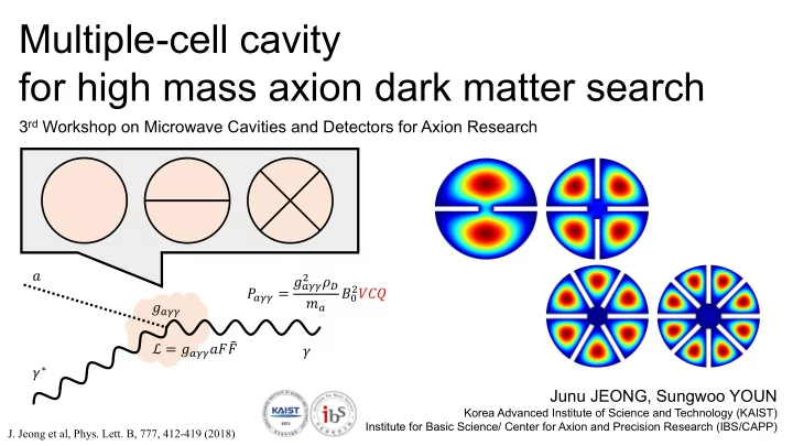
Multiple-cell cavity for high mass axion dark matter search
Junu JEONG, Sungwoo YOUN
Korea Advanced Institute of Science and Technology (KAIST) Institute for Basic Science/ Center for Axion and Precision Research (IBS/CAPP)
3rd Workshop on Microwave Cavities and Detectors for Axion Research
𝑏 𝛿∗ 𝛿 %&& ℒ = %&&𝑏𝐺𝐺 * 𝑄
%&& = %&& ,
𝜍. 𝑛% 𝐶1
,𝑊𝐷𝑅
- J. Jeong et al, Phys. Lett. B, 777, 412-419 (2018)