SLIDE 1
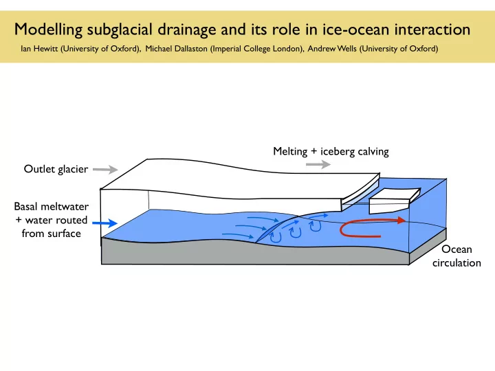
Modelling subglacial drainage and its role in ice-ocean interaction
Ian Hewitt (University of Oxford), Michael Dallaston (Imperial College London), Andrew Wells (University of Oxford)
Outlet glacier Basal meltwater + water routed from surface Ocean circulation Melting + iceberg calving
SLIDE 2
- I. What do models tell us about how subglacial discharge is delivered at grounding lines?
- II. How does the spatial distribution of subglacial discharge affect the shape of ice shelves?
SLIDE 3
Permeable sediments ‘Distributed’ systems ‘Channel’ systems
Subglacial drainage
SLIDE 4 Zs Zb / r = ⇢wgZb + pw
Hydraulic potential Discharge (turbulent flow)
Q = −KcS4/3
@s
@s
Channel dynamics
N = pi − pw
Ice creep Melting
S
Cross-sectional area
∂S ∂t = ρw ρi M − 2A nn S|N|n−1N ⇤ ⇤
Röthlisberger 1972, Nye 1976
M = −1 − ⇢wc ⇢wL Q@ @s − ⇢wgc L Q@Zb @s
- Most of the potential energy dissipated by turbulence is converted to latent heat
Q
SLIDE 5 Steady-state channel with constant discharge
Zs Zb Z = /⇢wg p S U = Q/S
- Melting rate and creep closure rate are reduced near grounding line.
- Results in trumpet-like shape of channels, and relatively low water speed at outlet.
Channel dynamics
SLIDE 6 Zs Zb Z = /⇢wg p ∂S ∂t + ub · rS = ρw ρi M 2A nn SN n S U = Q/S
- However, advection of channels with the ice prevents them becoming too large
With advection
Steady-state channel with constant discharge
Channel dynamics
- Further analysis indicates outflow water speed
C ⇡ 3 m1/4 s27/44 U ⇡ CQ2/11u9/44
b
(sin ✓)9/44
SLIDE 7 General comments
- Routing of subglacial water controlled primarily by topography
(probably largest factor in determining portal locations).
- Subglacial drainage system exhibits instabilities that likely lead to
episodic discharge (in addition to weather-driven episodes).
- Expect large seasonal signal of subglacial discharge when
surface meltwater present.
SLIDE 8
- I. What do models tell us about how subglacial discharge is delivered at grounding lines?
- II. How does the spatial distribution of subglacial discharge affect the shape of ice shelves?
SLIDE 9 Gladish et al 2012
5 10 15 5 10 15 20 25 30 35 Across-shelf distance (km)
c
50 100 150 200 5 10 15 5 10 15 20 25 30 35 Across-shelf distance (km)
b
10 20 30 40 50 60
N
stagnant ambient layer ice shelf active ocean layer inflow boundary
20 km 600m −τ0 40 km v0 τ0 z = b(x, y, t) z = a(x, y, t) z = s(x, y, t) z y x
Previous modelling results
(a) (c)
Sergienko 2013 Melt rate Plume thickness Melt rate Channel depth Petermann ice shelf
SLIDE 10
A simplified model - ice
Depth-integrated model for ice shelf (standard)
∂h ∂t + r · (hu) = (ρo/ρi)m, ∂ ∂x 2ηh ✓ 2∂u ∂x + ∂v ∂y ◆ + ∂ ∂y ηh ✓∂u ∂y + ∂v ∂x ◆ (1 ρi/ρo) ρigh∂h ∂x = 0, ∂ ∂x ηh ✓∂u ∂y + ∂v ∂x ◆ + ∂ ∂y 2ηh ✓∂u ∂x + 2∂v ∂y ◆ (1 ρi/ρo) ρigh∂h ∂y = 0,
Parameterised interface melting
mL = cγT |U|(T Tm).
U T
Ta
Tm
S
Sa
m
∝ h
D
x z
u
z = b(x, y, t)
y
Qg
e
+ prescribed ice depth and speed over grounding line
SLIDE 11
A simplified model - plume
r · (DU) = e + m, r · (DUU) = DgβSS∆ ✓ ∂b ∂x ∂D ∂x ◆ + r · (κDrU) Cd|U|U r · (DUV ) = DgβSS∆ ✓ ∂b ∂y ∂D ∂y ◆ + r · (κDrV ) Cd|U|V r · (DUS) = eSa + r · (κDrS) + mSi, r · (DUT) = eTa + r · (κDrT) + mTm mL c .
Simplified plume model (conservation laws) Parameterised entraiment e = E0|U||⌅b|, Turbulent eddy viscosity Along slope buoyancy due to salinity (coupling to ice dynamics) (smooths small-scale velocity differences) Heat exchange with ice + prescribed subglacial discharge at grounding line
U
T
Ta
Tm
S
Sa
m
∝ h
D x
z
u
z = b(x, y, t)
y
Qg
e
SLIDE 12 One-dimensional steady-state ice-shelf shape (melting rate approximately uniform)
- Small transverse perturbation of arbitrary wavenumber
Larger subglacial discharge
(b) ˜ hg ˜ h(x) y
Reduced model results
0.2 0.4 0.6 0.8 1 1.2 1.4 1.6 1.8 2 −1 surface s base b x
Linear stability analysis (due to variable grounding-line ice depth or variable subglacial discharge)
SLIDE 13 Ice depth perturbation
50 100 150 10−1 100 101 102 ice unreg. (ν = 0) ν = 0.002 ν = 0.02 k X/2) δ = 0 δ = 0.036 (d)
Amplitude of perturbation
Wave number of perturbation
- Perturbations at grounding line grow downstream, driven by transverse flow into
channels and enhanced buoyancy-driven acceleration.
- Stabilisation of small wavelengths is due to turbulent mixing in the plume layer.
- Transverse ice flow is relatively ineffective at smoothing out channels.
Dallaston, Hewitt & Wells, in review
Reduced model results
SLIDE 14
Summary
Subglacial drainage channels are likely to trumpet out near grounding line. Expect a smooth transition from subglacial melting (potential energy) to frontal melting (ocean heat). Uneven spatial distribution of discharge and/or basal topography at grounding line can cause channelisation due to enhanced melting of the shelf. Primary factors in channelisation are flow-focussing and buoyancy-driven acceleration, counteracted by turbulent mixing.