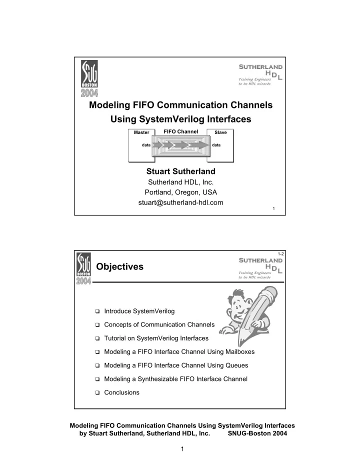
modeling fifo communication channels using systemverilog
play

Modeling FIFO Communication Channels Using SystemVerilog Interfaces - PDF document

Modeling FIFO Communication Channels Using SystemVerilog Interfaces FIFO Channel Master Slave data data Stuart Sutherland Sutherland HDL, Inc. Portland, Oregon, USA stuart@sutherland-hdl.com 1 1-2 Objectives Introduce SystemVerilog


  1. Modeling FIFO Communication Channels Using SystemVerilog Interfaces FIFO Channel Master Slave data data Stuart Sutherland Sutherland HDL, Inc. Portland, Oregon, USA stuart@sutherland-hdl.com 1 1-2 Objectives � Introduce SystemVerilog � Concepts of Communication Channels � Tutorial on SystemVerilog Interfaces � Modeling a FIFO Interface Channel Using Mailboxes � Modeling a FIFO Interface Channel Using Queues � Modeling a Synthesizable FIFO Interface Channel � Conclusions Modeling FIFO Communication Channels Using SystemVerilog Interfaces by Stuart Sutherland, Sutherland HDL, Inc. SNUG-Boston 2004 1

  2. 1-3 What is SystemVerilog? � SystemVerilog extends of the IEEE 1364 Verilog standard � New design modeling capabilities � Abstract C language data types � More accurate RTL coding � Interfaces for communication � New verification capabilities � Assertions � Race-free testbenches � Object-oriented test programs � SystemVerilog is the next generation of the Verilog standard � Gives Verilog a much higher level of modeling abstraction � Gives Verilog new capabilities for design verification Mile High View of SystemVerilog SystemVerilog from C / C++ assertions mailboxes 3.1a test program blocks semaphores classes dynamic arrays clocking domains constrained random values inheritance associative arrays process control direct C function calls strings references interfaces packages int globals break nested hierarchy 2-state modeling shortint enum continue unrestricted ports packed arrays longint typedef return 3.0 automatic port connect array assignments byte structures do–while enhanced literals queues shortreal unions ++ -- += -= *= /= time values and units unique/priority case/if void casting >>= <<= >>>= <<<= specialized procedures compilation unit space alias const &= |= ^= %= Verilog-2001 standard file I/O (* attributes *) multi dimensional arrays ANSI C style ports $value$plusargs configurations generate signed types localparam `ifndef `elsif `line memory part selects automatic constant functions @* variable part select ** (power operator) Verilog-1995 modules $finish $fopen $fclose initial wire reg begin–end + = * / parameters $display $write disable integer real while % function/tasks $monitor events time for forever >> << always @ `define `ifdef `else wait # @ packed arrays if–else assign `include `timescale fork–join 2D memory repeat Modeling FIFO Communication Channels Using SystemVerilog Interfaces by Stuart Sutherland, Sutherland HDL, Inc. SNUG-Boston 2004 2

  3. 1-5 Verilog, SystemVerilog and SystemC � Each hardware design language has unique capabilities � This paper is not about what language is best � This paper is on how SystemVerilog enables modeling inter- module communication at a higher level of abstraction � This chart shows... SystemC Software and embedding programming � SystemVerilog does not replace SystemC Verilog Object Oriented programming with � SystemVerilog bridges System- Verilog a gap between Verilog Behavioral and VHDL transaction modeling and SystemC Verilog RTL modeling Gate-level modeling Chart reflects the author’s perception Switch-level modeling of general language overlap 1-6 What’s Next � Introduce SystemVerilog � Concepts of Communication Channels � Tutorial on SystemVerilog Interfaces � Modeling a FIFO Interface Channel Using Mailboxes � Modeling a FIFO Interface Channel Using Queues � Modeling a Synthesizable FIFO Interface Channel � Conclusions Modeling FIFO Communication Channels Using SystemVerilog Interfaces by Stuart Sutherland, Sutherland HDL, Inc. SNUG-Boston 2004 3

  4. 1-7 Inter-Module Communication � Verilog connects models using detailed module ports � Each discrete signal must be declared as a port � SystemC provides communication channels � Encapsulate how information is transferred between modules � Allow abstract, high-level communication � SystemVerilog has communication interfaces � Encapsulate how information is transferred between modules � A new paradigm for inter-module communication Can SystemVerilog interfaces provide the same abstract communication capabilities as SystemC channels? Can SystemVerilog interfaces be synthesized? 1-8 SystemC Channels � SystemC provides channels and interfaces � A “channel” encapsulates how information is transferred between blocks of a design � An “interface” defines a set of methods (functions) to send and receive data through the channel � There are two types of channels � Built-in channels that are pre-defined in SystemC � Includes FIFO, Mutex, and Semaphore channels � Represent abstract communication � Generally not synthesizable � User-defined channels � Can be modeled as abstract or at a more detailed level � Can be synthesizable Modeling FIFO Communication Channels Using SystemVerilog Interfaces by Stuart Sutherland, Sutherland HDL, Inc. SNUG-Boston 2004 4

  5. 1-9 A SystemC FIFO Channel � FIFOs are typically used to communicate between design blocks that operate on different, asynchronous clocks � The SystemC built-in FIFO channel: � Is unsized — any amount of data can be in the channel � Is untyped — any data type can be sent through the channel � Provides write/read methods to send data through the channel � Methods are built-in — end user does not see how they work MASTER SLAVE module module read packet method data packet write pointer ... read pointer data packet write data packet method packet 1-10 What’s Next � Introduce SystemVerilog � Concepts of Communication Channels � Tutorial on SystemVerilog Interfaces � Modeling a FIFO Interface Channel Using Mailboxes � Modeling a FIFO Interface Channel Using Queues � Modeling a Synthesizable FIFO Interface Channel � Conclusions Modeling FIFO Communication Channels Using SystemVerilog Interfaces by Stuart Sutherland, Sutherland HDL, Inc. SNUG-Boston 2004 5

  6. 1-11 Inter-Module Communication: Verilog Style module MASTER (input clock, � Verilog connects modules at inout [31:0] data, output [15:0] address, the implementation level Connection details output request, input grant, are in the module MASTER SLAVE input ready ); module data module ... address module SLAVE (input clock, request inout [31:0] data, grant Connection details input [15:0] address, input request, ready are duplicated in output grant, clock other modules output ready ); ... I want to be an engineer, module top (input clock); not a typist! wire [31:0] data, wire [15:0] address, Netlists must duplicate wire request, grant, ready; the connection detail (yet again) MASTER i1 (clock, data, address, request, grant, ready); SLAVE i2 (clock, data, address, request, grant, ready); endmodule 1-12 Inter-Module Communication: SystemVerilog Style � Interfaces encapsulate Connection details interface BUS; are in the interface inter-module communication wire [31:0] data; logic [15:0] address; BUS logic request, grant, ready; MASTER SLAVE endinterface module data module address module MASTER (interface io_bus); request ... grant endmodule ready clock module SLAVE (interface io_bus); ... Modules and netlist do not endmodule Now I can concentrate on duplicate the connection details designing instead of typing! module top (input clock); instantiate the interface BUS io (); ( io is the instance name) MASTER i1 (io, clock); SLAVE i2 (io, clock); endmodule connect interface instance to module port Modeling FIFO Communication Channels Using SystemVerilog Interfaces by Stuart Sutherland, Sutherland HDL, Inc. SNUG-Boston 2004 6

  7. 1-13 Interface Modports � The module’s port direction definitions are moved to within the interface, using the modport keyword (for “module’s ports”) � Encapsulates port lists that used to be scattered in many modules interface BUS ; wire [31:0] data; BUS MASTER SLAVE logic [15:0] address; data module module logic request, grant, ready; address modport master_ports (inout data, request output address, grant A modport defines the output request, ready port directions from the input grant, module’s point of view clock input ready ); modport slave_ports (inout data, input address, input request, output grant, output ready ); endinterface 1-14 Selecting Which Modport Definition To Use � SystemVerilog has two ways to select which modport to use � At the module instance — allows “generic module ports” interface BUS; module MASTER (interface io_bus); modport master_ports (...) ... endmodule modport slave_ports (...) connect to interface using endinterface module top (input clock); the master_ports port list BUS io (); Each instance of the module can MASTER i1 (io.master_ports, clock); be connected to a different ... interface or a different modport endmodule � At the module instance — prevents incorrect corrections interface BUS; module SLAVE (BUS.slave_ports io_bus); modport master_ports (...) ... connect to interface using endmodule modport slave_ports (...) the slave_ports port list endinterface module top (input clock); Hard coded interface port means BUS io (); ... each instance of the module will SLAVE i2 (io, clock); be connected the same way endmodule Modeling FIFO Communication Channels Using SystemVerilog Interfaces by Stuart Sutherland, Sutherland HDL, Inc. SNUG-Boston 2004 7

Download Presentation
Download Policy: The content available on the website is offered to you 'AS IS' for your personal information and use only. It cannot be commercialized, licensed, or distributed on other websites without prior consent from the author. To download a presentation, simply click this link. If you encounter any difficulties during the download process, it's possible that the publisher has removed the file from their server.

Recommend


More recommend