Mexican Collaborations - Projects XPLORE, XIBALBA, and XIB_TCS - - PowerPoint PPT Presentation

mexican collaborations projects xplore xibalba and xib
SMART_READER_LITE
LIVE PREVIEW

Mexican Collaborations - Projects XPLORE, XIBALBA, and XIB_TCS - - PowerPoint PPT Presentation

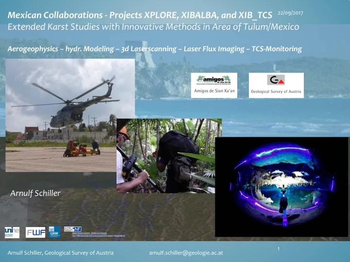
22/09/2017 Mexican Collaborations - Projects XPLORE, XIBALBA, and XIB_TCS Extended Karst Studies with Innovative Methods in Area of Tulum/Mexico Aerogeophysics hydr. Modeling 3d Laserscanning Laser Flux Imaging TCS-Monitoring


slide-1
SLIDE 1

22/09/2017 1 Arnulf Schiller, Geological Survey of Austria arnulf.schiller@geologie.ac.at

Mexican Collaborations - Projects XPLORE, XIBALBA, and XIB_TCS Extended Karst Studies with Innovative Methods in Area of Tulum/Mexico

Aerogeophysics – hydr. Modeling – 3d Laserscanning – Laser Flux Imaging – TCS-Monitoring

Arnulf Schiller

slide-2
SLIDE 2

22/09/2017 2 Arnulf Schiller, Geological Survey of Austria arnulf.schiller@geologie.ac.at

Hol Box fracture zone

Cancun Tulum

The Survey Area – Tulum Karst Plain

  • huge and difficult accessible coastal karst plain covered

with forests, mangroves and lagoons

  • variably consolidated limestones several 1000 metres

thick.

  • thin soil cover – limestone exposed at the surface
  • flat topography

(0 - ~ 50 m above mean sea level)

  • known conduits/ caves system explored by cave divers
  • freshwater layer above saltwater body
  • tidal variation of groundwater and halocline level reaching inland
  • socio-economic impact due to urban development and increasing water demand
  • climate change
slide-3
SLIDE 3

22/09/2017 3 Arnulf Schiller, Geological Survey of Austria arnulf.schiller@geologie.ac.at

AEM Surveys Tulum 2007, 2008 and 2015: approx. 250 km2

slide-4
SLIDE 4

22/09/2017 4 Arnulf Schiller, Geological Survey of Austria arnulf.schiller@geologie.ac.at

Project XPLORE – Problem Statement and Methodology

  • Can AEM map the underground conduit system?
  • Can a Karst water regime be modelled by combining aerogeophysical and

hydrogeological input data? Methodology:

Pilot surveys, simulation of measurement situation – estimation of expected measurement signal AEM-Survey electrical conductivity in the subsurface (through 1D-inversion)

  • El. Conductivity

lateral and vertical distribution of hydrogeological relevant structures (due to distribution of porosity, water saturation, ion concentration, permeability, GWL, halocline) – Map of potential conduits. Structural information from AEM and underwater cave surveys Groundwater model (UNINE) Calibration of AEM-measurements and groundwater model by ground survey data (ERT, bore hole geophysics, piezometry, GPR) Archie‘s law (Archie 1942)

slide-5
SLIDE 5

22/09/2017 5 Arnulf Schiller, Geological Survey of Austria arnulf.schiller@geologie.ac.at

The measurement system

slide-6
SLIDE 6

22/09/2017 6 Arnulf Schiller, Geological Survey of Austria arnulf.schiller@geologie.ac.at

Helicopter provided by the Mexican Marina (MilMi - 8)

slide-7
SLIDE 7

22/09/2017 7 Arnulf Schiller, Geological Survey of Austria arnulf.schiller@geologie.ac.at

Survey area as seen from helicopter

slide-8
SLIDE 8

22/09/2017 8 Arnulf Schiller, Geological Survey of Austria arnulf.schiller@geologie.ac.at

load specialist Bird 30 m below the helicopter

slide-9
SLIDE 9

The 2007/2008 AEM surveys –first results

known caves are detected – some indication of further conduits

22/09/2017 Arnulf Schiller, Geological Survey of Austria arnulf.schiller@geologie.ac.at 9 Halfspace inversion from 3k_in, 7k_in – phases (2007/2008) Edited and height reduced raw signal (ppm) of all inphase components (2007)

slide-10
SLIDE 10

22/09/2017 10 Arnulf Schiller, Geological Survey of Austria arnulf.schiller@geologie.ac.at

Estimated topography of halocline AEM-data inversion

surface layer and two sections (software: UBC EM1DFM)

Resistivity ranges found: Above halocline: 10 to 200 Ohmm Below halocline 0.7-50 Ohmm Seawater: 0.2-0.25 Ohmm Freshwater: around 4 Ohmm Brakish water: around 1 Ohmm

slide-11
SLIDE 11

How to get out more information?

adapting AEM pre/post-processing for enhancing signals of possible conduits

22/09/2017 Arnulf Schiller, Geological Survey of Austria arnulf.schiller@geologie.ac.at 11

* Pre-Inversion-Processing (on raw/ppmdata)

1) System drift analysis 2) Automatic drift correction 3) Estimation and correction of residual drift by analysis of vertical field gradient. 4) De-stripping (type of levelling) 5) Qualitycontrol/editing

* 1D-Inversion (UBC EM1DFM) * Processing of inversion results:

  • De-stripping (type of levelling).
  • Reduction of vertical gradient

2007/2008 f3_in , reduced to 40 meters above ground, meanfree.

slide-12
SLIDE 12

22/09/2017 12 Arnulf Schiller, Geological Survey of Austria arnulf.schiller@geologie.ac.at

Sections

Detection of fresh water layer, mixing zone and salt water saturared limestone

~ 10 km

50 m depth Electrical Conductivity Log10[S/m] reef Low wet land Fresh water layer (blue) Salt water body (yellow-red) Line YUK001, 2008-survey

slide-13
SLIDE 13

22/09/2017 13 Arnulf Schiller, Geological Survey of Austria arnulf.schiller@geologie.ac.at

Background reduced sections crossing surveyed cave system

slide-14
SLIDE 14

22/09/2017 14 Arnulf Schiller, Geological Survey of Austria arnulf.schiller@geologie.ac.at

Results: Overview of conduit network (from 2007 and 2008 AEM data )

slide-15
SLIDE 15

22/09/2017 15 Arnulf Schiller, Geological Survey of Austria arnulf.schiller@geologie.ac.at

Inversion line YUK001 (2008) – section of reef structure?

slide-16
SLIDE 16

22/09/2017 16 Arnulf Schiller, Geological Survey of Austria arnulf.schiller@geologie.ac.at

Example: Geoelectrics and GPR

slide-17
SLIDE 17

Conclusion of AEM survey in Tulum Karst:

  • Halocline level is well resolved.
  • GWL is not clearly resolved in AEM (capillary effects ? Frequency problem?).
  • Interpretation of Halocline with conductivity isosurface problematical (varying

porosity).

  • Distribution of electrical conductivity derived from AEM correlates to surveyed caves

and yields picture of potential karst conduit distribution - lateral and in depth.

  • Structures also visible at the reef (saltwater cover) and in lagoon area (brakish water

cover)

Questions:

  • How can the GWL be better resolved?
  • Is it possible to resolve structures below seawater (shielding?)

22/09/2017 Arnulf Schiller, Geological Survey of Austria arnulf.schiller@geologie.ac.at 17

slide-18
SLIDE 18

22/09/2017 18 Arnulf Schiller, Geological Survey of Austria arnulf.schiller@geologie.ac.at

Gracias!

slide-19
SLIDE 19

22/09/2017 19 Arnulf Schiller, Geological Survey of Austria arnulf.schiller@geologie.ac.at

Models System Layered halfspace Halfspace with conduits

Emigma, 1d