METAL-MATRIX HEAT-RESISTANT FIBROUS COMPOSITES Mileiko, S.T. Solid - - PDF document

metal matrix heat resistant fibrous composites
SMART_READER_LITE
LIVE PREVIEW

METAL-MATRIX HEAT-RESISTANT FIBROUS COMPOSITES Mileiko, S.T. Solid - - PDF document

18 TH INTERNATIONAL CONFERENCE ON COMPOSITE MATERIALS METAL-MATRIX HEAT-RESISTANT FIBROUS COMPOSITES Mileiko, S.T. Solid State Physics Institute, Chernogolovka, Moscow distr., 142432, Russia (mileiko@issp.ac.ru) Keywords : metal-matrix


slide-1
SLIDE 1

18TH INTERNATIONAL CONFERENCE ON COMPOSITE MATERIALS

1 Introduction A far-reaching way to enhance temperature in various gas turbines and other machines is to replace superalloys and homogeneous ceramics with fibrous

  • composites. This idea is now rather obvious;

however, ways of the realisation are complicated and despite the composite community has been going along these ways for about 40 years we are now observing a success just in few directions, the development of SiC/SiC composites is perhaps a most successive one [1]. Heat-resistant metal-matrix composites (MMCs) are now in shadow but recent results obtained by the author’s research group are formed a base for the hopes. These results have become possible due to (i) the invention of the internal crystallisation method for producing single crystalline and eutectic oxide fibres suitable for the use in structural applications [2] and (ii) an intensive use of micromechanical models of creep [ 3

ε 

] in planning the experiments and interpreting their results. In the present paper, these results are briefly

  • reviewed. We are to start with a creep model for

MMCs and its applications to analysing creep behaviour of various composite macrostructures, which is necessary to evaluate creep properties of a rather large variety of possible composites, then will proceed with fabrication technology of appropriate fibres and composites reinforced with them, and finally present creep behaviour of the composites. We are to conclude with a discussion of the prospects of such type of the composites. 2 Creep model 2.1 The basic The basic model of creep behaviour of MMCs was published some years ago [2]. The model yields a dependence between composite stress σ and creep rate

  • n the steady state as

( )

m m m m f n m n m

  • m

f

  • m

V V d l

1 1 1

        +                               =

+

η ε σ η ε λσ σ λσ σ

β

 

(1) where matrix characteristics are connected to the power low of matrix creep,

m m m 1

        = η ε σ σ  ; fibre characteristics are determined by the Weibull based strength/fibre length dependence,

( )( ) ( )( )

β

σ σ

1 − ∗

        =

  • f
  • f

l l l l ; λ is a function of the fibre/matrix interface strength given by α 1 ≤ < α ; β β m m n + + = , d is a characteristic fibre diameter.

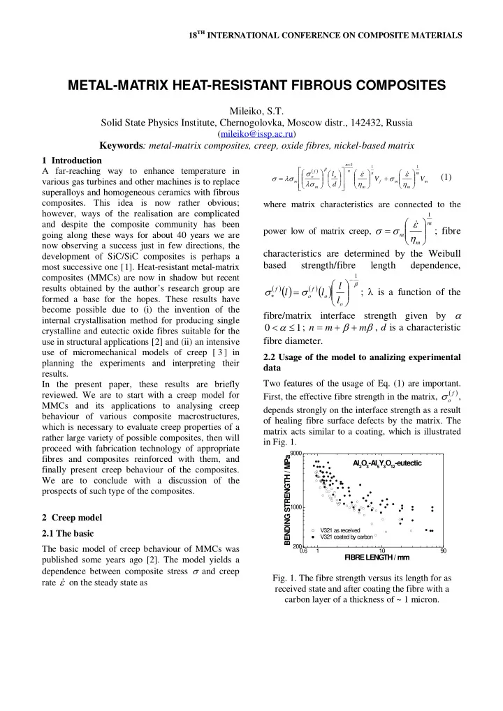
2.2 Usage of the model to analizing experimental data Two features of the usage of Eq. (1) are important. First, the effective fibre strength in the matrix,

( )

f

  • σ

, depends strongly on the interface strength as a result

  • f healing fibre surface defects by the matrix. The

matrix acts similar to a coating, which is illustrated in Fig. 1.

0.6 1 10 90 200 1000 9000

Al2O

3-Al5Y 3O 12-eutectic

V321 as received V321 coated by carbon

BENDING STRENGTH / MPa FIBRE LENGTH / mm

  • Fig. 1. The fibre strength versus its length for as

received state and after coating the fibre with a carbon layer of a thickness of ~ 1 micron.

METAL-MATRIX HEAT-RESISTANT FIBROUS COMPOSITES

Mileiko, S.T. Solid State Physics Institute, Chernogolovka, Moscow distr., 142432, Russia

(mileiko@issp.ac.ru)

Keywords: metal-matrix composites, creep, oxide fibres, nickel-based matrix

slide-2
SLIDE 2

This yields a necessity to connect a value of the effective fibre strength in a composite to the value of the interface strength given by α.

Secondly, the model described allows replacing relationship (1) by a simple power low normally accepted while interpreting experimental data on creep of any materials [4

q

C

/ 1

ε σ  =

]. An important point is a possibility to calculate the value of exponent q in the approximation (2) Rewriting Eq. (1) as

m m n f

V B AV

/ 1 / 1

) 1 ( ε ε σ   − + =

(3) where A, B and C are combinations of the constants in the relationships written in the original form and looking for values of q and C, which provide the best approximation of Eq. (3) with Eq. (2), which means to provide a minimum to the integral

( )

, d ) 1 (

2 1

2 / 1 / 1 / 1

− − + = Σ

ε ε  

x Cx x V B x AV

q m m n f

(4)

in which the limits of integration are the limits of creep rates of interest. In the present context they are 10-4 and 10-1 h-1. An example of the calculated values of q is presented in Fig. 2.

  • Fig. 2. Calculated value of exponent q in a power

function approximating creep-rate/stress dependence

  • f a composite.

It is important to note that the values of the exponent at fibre volume fractions sufficiently high are much larger than the value of m. This has a clear physical meaning since creep behavior of a composite with a large fibre volume fraction is determined by the fibre strength. A comparison of exponent q calculated and the exponent values obtained in the experiments with 2- steps loading of specimens is presented in Fig. 3. Obviously, the calculation yields an acceptable result.

  • Fig. 3. Calculated values of the exponent, q, and the

values obtained in the experiments. The values of structural parameters are as follows: m = 5, β = 3, l0=1 mm, d = 0.1 mm, α = 0.4, which corresponds to the effective fibre strength equal to 600 MPa. The creep model just described allows analysing an effect of a non-homogeneous fibre packing in the cross-section of a composite specimen. Fibre clustering can affect essentially creep properties of

  • xide-fibre/Ni-based-matrix composites with a non-

ideal interface. It is mainly due to a fact that in some systems in that family of the composites the interface strength goes down at fibre volume fractions Vf larger than some value of Vf [5

  • Fig. 2

]. This means that the interface strength within the clusters can be lower than that outside of the clusters. At the same time, the value of exponent q depends strongly

  • n fibre volume fraction (

). Therefore, a problem of creep of a composite rod with non- homogeneous fibre packing occurs to be non-linear and hardly can be solved analytically. Hence, we present simple solution for a model specimen just to illustrate potential effects semi-qualitatively. Let a specimen has two kinds of the fields of equal areas, one containing fibre clusters with volume fraction 2Vf, and another field being a pure matrix; so that the average fibre volume fraction in both specimens is Vf. Consider, first, the case of the interface strength independent of fibre volume

  • fraction. A simple calculation of creep resistance of

specimen yields results shown in Fig. 4.

slide-3
SLIDE 3

3

Metal-matrix heat-resistant fibrous composites

  • Fig. 4. Calculated dependencies of creep resistance
  • f model composites with homogeneous and non-

homogeneous fibre distribution in the cross-section. The values of interface strength and effective fibre strength are taken as α = 0.4,

( )

f

  • σ

= 600 MPa; α = 0.1,

( )

f

  • σ

= 300 MPa; α = 0.025,

( )

f

  • σ

= 150 MPa. (Note that as mentioned above, the fibre effective strength depends on the interface strength.) It can be seen that creep resistance of the composites with strongly non-homogeneous fibre packing is not lower than that for a composite with homogeneous fibre packing. A reason for such behaviour of composites with non-homogeneous fibre distribution is clear, it is a result of a strong non-linear dependence of exponent q on fibre volume fraction,

  • Fig. 2, which yields a non-linear dependence of the

creep resistance on fibre volume fraction. In the case when the interface strength depends on fibre volume fraction the creep-resistance/fibre- volume-fraction dependence goes along a curve corresponding to a large value of α and then moves to curves corresponding to smaller and smaller α.

Two consequences follow. First, a general dependence of the creep resistance on fibre volume fraction has a maximum at some values

  • f Vf. This has been observed earlier [3].

Secondly, deviation of the fibre distribution from a homogeneous one shifts the maximum to smaller values of Vf.

3 Fabrication technology Single crystalline and eutectic fibres are produced by the internal crystallysation method that allows crystallizing a bundle containing hundredths and thousands of the fibres [2]. The fibres obtained and used in the composites up to the present time are single crystalline sapphire and YAG as well as eutectics Al2O3-Al5Y3O12 (AY), Al2O3-Er5Y3O12 (AEr), Al2O3-Al5Y3O12-ZrO2 (AYZ), LaAl11O18- AlLaO3 (ALa) Two commercially available superalloys [6,7] have being used as matrix materials. The alloy marked as VKNA-4U contains Al, Cr, W, Ti, Co, Mo and C. That marked as VKNA-25 differs from VKNA-4U by the presence of 3.5% Rhenium. Composite specimens were obtained by pressure infiltration of a fibre bundle placed in quartz ampoule [8 Creep experiments are carried out on cylindrical specimens loaded in bending by either step-wise loading and in such case the value of q is determined directly or by a single load, in which case q is

  • calculated. Then tensile creep characteristics of the

composites are calculated by using a solution of the creep problem for a beam under bending. A corresponding procedure is described in details in [ ]. Temperature and pressure of argon gas in the infiltration process were 1550oC and 0.5 MPa,

  • respectively. Crystallisation of the matrix was

performed in the axial temperature gradient to make a single crystalline microstructure of the matrix. The diameter and length of the specimens were ~5 and ~50 mm, respectively. 4 Creep behavior of oxide-fibre/nickel-matrix

composites

3]. Some examples of dependencies of the creep resistance (accepted as a stress to cause 1% creep strain for 100 h) on fibre volume fraction are presented in Fig. 5. It can be seen that for a particular composition creep resistance can reach a value of 150 MPa at a temperature of 1150oC. It is important to point out that the density

  • f

the composites under consideration is between 6.5 and 6.8 g/cm3 at sufficiently high fibre volume fraction, At the same time the density of modern superalloys are approaching 9 g/cm3.

slide-4
SLIDE 4

0.0 0.1 0.2 0.3 0.4 30 40 50 60 70

Creep resistance / MPa Fibre volume fraction

Sapphire/VKNA-4U

0.0 0.1 0.2 0.3 0.4 30 40 50 60 70

Al2O3-Al5Y

3O12/VKNA-4U

Creep resistance / MPa Fibre volume fraction

0.00 0.05 0.10 0.15 0.20 0.25 0.30 0.35 0.40 0.45 60 80 100 120 140 160

Creep resistance / MPa Fibre volume fraction

AYZ/VKNA-25

Non-hompgeneous fibre packing

0.2 0.3 0.4 0.5 0.6 0.7 25 50 75 100 125

a1996 a1997 a1998 a4001 a4002 a4003 a4004

Creep resistance / MPa

Fibre volume fraction LaAl11O18-AlLaO3/VKNA-25, 1150

  • C

0.25 0.30 0.35 0.40 110 115 120 125 130 135

a4007 a4008 a4009

Creep resistance / MPa Fibre volume fraction AEr/VRNA-25, 1150

  • C
  • Fig. 5. Creep resistance of oxide-fibre/Ni-based-

alloy matrix composites versus fibre volume fraction at 1150oC. A compilation of the data presented in Fig. 5 is plotted in Fig. 6 as a dependence of the maxima of creep resistance of the composites reinforced with various oxide fibres on fibre volume fraction. Such presentation that shows by arrows possible developments being not completely rigorous demonstrate clearly an effect

  • f

particular fibre/matrix combinations on the creep properties in this family of composites.

0.15 0.20 0.25 0.30 0.35 0.40 0.45 60 80 100 120 140 160

Creep resistance / MPa Fibre volume fraction Sapphire fibre AY AL AEr AYZ

  • Fig. 6. Maxima of the creep resistance of various

composites. 5 Prospects of heat-resistant MMCs The history of development of the Ni-based heat- resistant Ni-based alloys is presented in Fig. 7. It is clear that at the present time the maximum use temperature of MMCs can be between 1150 and 1200oC as compared with 1100oC for prospective superalloys. A further increase in the use

slide-5
SLIDE 5

5

Metal-matrix heat-resistant fibrous composites

temperature will be possible if matrices with higher melting point are available.

1940 1950 1960 1970 1980 1990 2000 2010 2020 800 1000 1200 1400

OXIDE/ME??- ??-Fut utur ure TEMPERATURE /

оС

YEARS OXI XIDE/ E/Ni -

  • C

COMPO POSI SITES ES WROUGHT CAST DIRECTIONALLY SOLIDIFIED SINGLE CRYSTALLINE Future Present

  • Fig. 7. Retrospective and prospects of Ni-based heat-

resistant alloys as dependence of the maximum use temperature on the year of the development. Also state of the art of the composite with the prospects is

  • shown. The use temperature of superalloys is

defined as that to provide stress rupture equal to 150 MPa on the 1000 h time base.

  • 6. Main conclusions
  • 1. An intensive use of the micromechanical

model in planning the experiments and interpreting their results and developing express methods of creep testing allows speeding up a process of development of creep resistant composites essentially. This has given a possibility to perform creep testing of a large number of the composites

  • 2. The present stage of the development is

characterized by oxide-fibre/nickel-based composites of a density as low as 6.5 – 6.8 g/cm3 with creep resistance at a temperature

  • f 1150oC reaching 150 MPa on a 100 h

base.

  • 3. The methodology of developing creep

resistant composites can be definitely used to obtain composites with better creep characteristics than those presented in the paper. Acnowledgments Financial support of Russian Foundation for Basic Research (projects 08-03-01068 and 11- 03-01239) is acknowledged. The author appreciates a contribution to the experimental part of the work his colleagues, Drs V.M. Kiiko, N.I. Novokhayskaya, A.N. Tolstun, A.A. Kolchin and Mrs. N.A. Prokopenko.

References

1 “High Temperature Ceramic Materials and

Composites”. Eds W. Krenkel and J. Lamon, AVISO, 2010. 2 Mileiko, S. T. “Single crystalline oxide fibres for heat-resistant composites”, Compos. Sci. and Technol., Vol 65,No 15-16 pp 2500-2513, 2005. 3 Mileiko, S. T. “Oxide-fibre/Ni-based matrix composites – III: A creep model and analysis of experimental data”, Compos. Sci. and Technol.,Vol. 62, No. 2, pp 195-204, 2002. 4 Mileiko, S. T., Kiiko, V. M., Kolchin, A. A., Novokhatskaya, N.I., Van, K. V., Bazyleva, O. A., Bondarenko, Yu. A. “Creep of oxide/nickel composites”, Composites and Nanostructures, No 4, pp 5-18, 2009. 5 Prokopenko, V.M. and.Mileiko, S.T, “Evaluation

  • f the fibre/matrix interface strength by the pushing-
  • ut of fibres of non-symmetrical cross-section”,
  • Compos. Sci. and Technol., Vol 61, No. 11, pp

1649-1652, 2001. 6 Buntushkin, V.P., Burkina, V.I., Timofeeva, O.B., Yushakova, F.V., “Composition, microstructure and properties of single crystalline alloy VKNA-25”, Aviation Materials and Technologies, No. 1, pp 10- 14, 2008 (in Russian). 7 Kablov, E.N., Buntushkin, V.P,, Povarova, K.B., Bazyleva, O.A., Morozova, G.I., Kazanskaya, N.K., “Low-alloyed light heat-resistant materials based on the Ni3Al intermellic”, Metally No. 1, pp 58-65, 1999 (in Russian). 8 Mileiko, S.T,, Kiiko.V,M., Kolchin, A.A., Serebryakov, A.V., Korzhov, V.P., Starostin, M.Yu., Sarkissyan, N.S., “Oxide-fibre/Ni-based matrix composites – I: Fabrication and microstructure”,

  • Compos. Sci. and Technol.,Vol. 62, No. 2, pp. 167-

179, 2002.