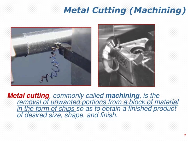
metal cutting machining
play

Metal Cutting (Machining) Metal cutting , commonly called machining , - PowerPoint PPT Presentation

Metal Cutting (Machining) Metal cutting , commonly called machining , is the removal of unwanted portions from a block of material in the form of chips so as to obtain a finished product of desired size, shape, and finish. 1 Metal Cutting


  1. Metal Cutting (Machining) Metal cutting , commonly called machining , is the removal of unwanted portions from a block of material in the form of chips so as to obtain a finished product of desired size, shape, and finish. 1

  2. Metal Cutting There are seven basic chip formation processes ● Shaping ● Drilling ● Turning ● Milling ● Sawing ● Broaching ● Abrasive machining 2

  3. Oblique Cutting Oblique Cutting : The cutting edge is set at an angle (the tool cutting edge inclination λ s ). This is the case of three-dimensional stress and strain conditions. 3

  4. Orthogonal Cutting Orthogonal cutting : The cutting edge is straight and is set in a position that is perpendicular to the direction of primary motion. This allows us to deal with stresses and strains that act in a plane. 4

  5. Orthogonal Cutting In order to better understand this complex process, the tool geometry is simplified from the three-dimensional (oblique) geometry, to a two-dimensional (orthogonal) geometry. Oblique Orthogonal 5

  6. Orthogonal Cutting Chip formation is a localized shear deformation resulting in the failure of the workpiece material immediately ahead of the cutting edges of the tool due to the force applied to the workpiece by the cutting tool, and relative motion between the tool and the workpiece. 6

  7. Orthogonal Cutting During orthogonal machining, shearing takes place along a plane making an angle, which is called the shear angle f , with the horizontal. This action transforms a volume of metal with thickness t and w (undeformed chip thickness and width, respectively) into a chip with thickness t c and width w. 7

  8. Metal Cutting Important observations during metal cutting are: 1. Distortion of the workpiece and the cutting tool due to the cutting force applied by the cutting tool. 2. Generation of heat due to the ● work required to deform the workpiece and the chip, ● friction between the face of the tool and the chip, ● friction between the flank of the tool and the workpiece. 8

  9. Temperature Distribution 9

  10. Effects of Work Material Properties Strength High-strength materials require larger forces than do materials of lower strength, causing greater tool and workpiece deflections; increased friction force and heat generation, and temperature; and requirement of greater work input. On the other hand, hard and abrasive constituents such as carbides in steel accelerate tool wear. 10

  11. Effects of Work Material Properties Ductility Ductility is an important factor. Highly ductile materials not only permit extensive plastic deformation of the chip during cutting, which increases work, heat generation, and temperature; but they also result in continuous chips which remain in contact longer with the tool face, thus causing more frictional heat generation. Chips of this type are severely deformed and have a characteristic curl. (Continuous chips) 11

  12. Effects of Work Material Properties Ductility Brittle materials cause small segments of chips due to the brittle failure along the shear zone. Such chips are called discontinuous or segmented chips, and provide fairly good surface finish. Are also observed when cutting with: • Small rake angle • Large depth of cut • Machining ductile materials at ● low cutting speed ● large feed 12

  13. Continuous Chip with Built-up Edge When cutting ductile materials with a high coefficient of friction, the local high temperature and extreme pressure in the cutting zone cause the work material to adhere or weld to the cutting edge of the tool forming a built- up edge. When the chip breaks down, the broken pieces are carried away by the underside of the chip and stick on the machined surface. 13

  14. Continuous Chip with Built-up Edge This type of chip is called continuous chip with built-up edge. This undesirable occurrence causes vibration, poor surface finish, and shorter tool life. Formation of built-up edge can be eliminated or minimized by 1) reducing the depth of cut; 2) increasing the cutting speed (while decreasing the depth of cut or/and feed); 3) increasing the rake angle; 4)using a cutting fluid (coolant). 14

  15. Types of Chips Discontinuous Continuous Continuous with (Segmented) built-up edge 15

  16. Tool Geometry The geometry of a single-point cutting tool is critical to the performance of the tool during metal removal. Important surfaces and angles on a typical HSS single- point cutting tool used in shaping or turning operations are: ● Face is surface of the tool over which the chip flows. ● Flank is the surface of the tool which is in contact with the workpiece. 16

  17. Tool Geometry Rake angles are used to define the inclination of the face. The face is inclined backwards with respect to the cutting edge, so that the chip is directed upward from the machined surface. Relief angles are used to define the inclination of the surfaces of the tool which are in contact with the workpiece (e.g. flank). These surfaces are inclined, so that the rubbing of the tool on to the workpiece is prevented. True rake is defined as the inclination of the tool face at the cutting edge as measured in the direction of actual chip flow. 17

  18. Cutting Tool Geometry - Single Point Cutting Tool 18

  19. Rake Angle For cutting mild steel the best rake angle is 10 - 20 degrees. Positive rake angle Increased strength Increased heat Easy cutting conduction capacity Reduced strength at tool neck and cutting edge Negative rake angle 19

  20. Tool Geometry Small rake angles cause high compression, tool forces, and friction which result a thick, highly deformed, hot chip. Large rake angles reduce compression, the forces, and the friction resulting in a thinner, less deformed, and cooler chip. On the other hand larger positive rake angles cause reduced strength of the cutting tool due to the reduced tool section and reduced capacity to conduct heat away from the cutting edge. In order to provide greater strength at the cutting edge and better heat conductivity, zero or negative rake angles are used on sintered carbide or ceramic cutting tools. 20

  21. Shear Plane Angle between tool face and shear plane is about 90 degrees. For the same depth of cut, increased rake angle increases the shear angle f and Depth of cut decreases the shear plane edge length. Thus it becomes possible to remove the chip with less f f f power. 21

  22. Chip Breakers As a chip breaker, a groove on the tool face is employed for deflection of the chip at a sharp angle and causing it to break into short pieces that are easier to remove and are not so likely to become tangled (dolaşma, karışma) in the machine and possibly cause damage to personnel. 22

  23. Chip Breakers Solid chip breakers are available in various lengths and angles to suit each metal cutting application. The adjustable chip breaker can eliminate the need for stocking various sizes of solid chip breakers. Solid Adjustable chip breaker chip breaker 23

  24. Cutting Tool Materials Cutting tool materials should have: 1. Strength, 2. Toughness to resist fracture, 3. Hardness and wear resistance at high temperatures, 4. Low coefficient of friction. ( 5. Favorable cost.) 24

  25. Cutting Tool Materials 2. High Speed Steel (HSS) (1900) Typical composition of this high alloy steel is 18-4-1 (tungsten 18%, chromium 4%, vanadium 1%). Retains its hardness at temperatures up to 600°C. Compared with tool steel, it can operate at about double the cutting speed with equal life, resulting in its name high- speed steel. HSS is widely used for drills and many types of general- purpose milling cutters and in single-point tools used in general machining. For high-production machining it has been almost completely replaced by carbides and coated tools. 25

  26. Cutting Tool Materials 3. TiN Coated High Speed Steel (HSS) (1980) Coated HSS provides significant improvements in cutting speeds, with increases of 10 to 20 % being typical. In addition to hobs, gear-shaper cutters, and drills; HSS tooling coated by TiN includes reamers, taps, chasers, spade-drill blades, broaches, band saw and circular saw blades, insert tooling, form tools, end mills, and an assortment of other milling cutters. Physical vapor deposition has proved to be the most viable process for coating. 26

  27. Cutting Tool Materials 4. Cemented Carbide (Sintered Carbide) (1947) Nonferrous alloys produced by powder metallurgy. The early versions, which are still widely used, had tungsten carbide as the major constituent and cobalt as a binder. Recent types of carbides utilize very fine micro particles dispersed (cemented) in the carbide structure (approx.10% TiC and TaC) for improving toughness and tool life. They can be operated at cutting speeds 200 to 500 % greater than those used for HSS, and they have replaced HSS in many processes. 27

  28. Cemented Carbide Many carbide tools are made in the form of throwaway inserts, having three to eight cutting edges, and are held mechanically in tool holders. When one cutting edge becomes dull, the insert is repositioned to a new edge; when all the edges become dull, it is thrown away. 28

Download Presentation
Download Policy: The content available on the website is offered to you 'AS IS' for your personal information and use only. It cannot be commercialized, licensed, or distributed on other websites without prior consent from the author. To download a presentation, simply click this link. If you encounter any difficulties during the download process, it's possible that the publisher has removed the file from their server.

Recommend


More recommend