SLIDE 1 SOLIDWORKS Advanced Sheet Metal
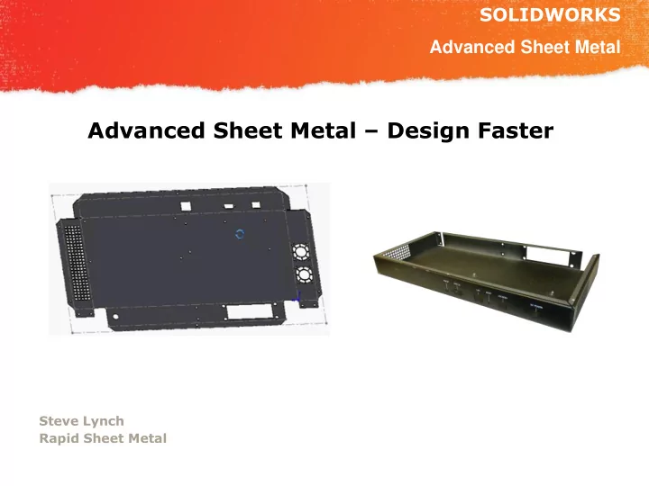
Advanced Sheet Metal – Design Faster
Steve Lynch Rapid Sheet Metal
SLIDE 2 SOLIDWORKS
NESWUC 2012
Intro
- Dedicated to quick turn prototype
sheet metal parts
- 15 seats of SolidWorks 2013
- CAD Quotes in under 8 hours
- Unfinished parts in 7 days
- Plated parts in 9 days
- We do not design parts
- 2,500 unique parts quoted a month
- n average
- Quoting & Manufacturing from 3D
CAD Data
SLIDE 3 SOLIDWORKS
NESWUC 2012
Overview
– How to find through hole size
– RSM web site table – Mate references – Hole Sizes +.003 -.000
– Forming tools from our web site
- Be careful with SolidWorks Sheet Metal Defaults
– Bend Radii – Material selection
– Add data to your part, Assembly, and Print fast!
- Welded box & cover with equations
– Save time, make it once – Get the idea completed and manufactured – Add welding locking features rapidly
- Advanced Bend Relief examples
– Using library feature – Using subtract bodies
SLIDE 4 SOLIDWORKS
NESWUC 2012
Overview Cont.
– Hem – Offset – Bump forming
– Use shell – Delete face – Get the idea down then engineer the design
- Pictures of before and after
– Welding – Solid parts cut for manufacturing
SLIDE 5
SOLIDWORKS
NESWUC 2012
Counter Sinks
82° Counter Sink in .119” steel. 82° Counter Sink in .047” steel.
SLIDE 6
SOLIDWORKS
NESWUC 2012
Counter Sinks
82° Counter Sink in .119” steel. 82° Counter Sink in .047” steel.
SLIDE 7
SOLIDWORKS
NESWUC 2012
Counter Sinks
82° Counter Sink in .047” thick steel.
SLIDE 8
SOLIDWORKS
NESWUC 2012
Counter Sinks
Ø.160
Ø.143 Before Ø.160 After Ø.017 Delta
SLIDE 9
SOLIDWORKS
NESWUC 2012
Counter Sinks
It’s better not dimensioning your through holes
SLIDE 10
SOLIDWORKS
NESWUC 2012
Hardware – RSM Hardware table
http://www.rapidsheetmetal.com/resources Rapid reference to Hardware data
SLIDE 11
SOLIDWORKS
NESWUC 2012
Hardware – Mate Reference
Problem Rivets and hardware with countersunk edges are hard to auto mate
SLIDE 12
SOLIDWORKS
NESWUC 2012
Hardware – Mate Reference
We have noticed it is common to select this top edge as the default Mate reference.
SLIDE 13
SOLIDWORKS
NESWUC 2012
Hardware – Mate Reference
We suggest adding a .001” extrude then a .0005” cut to the top face to create a 90° plane intersection to be used as the default mate reference
SLIDE 14
SOLIDWORKS
NESWUC 2012
Hardware – Mate Reference
Now as you drag this part from your library it will snap into place every time.
SLIDE 15
SOLIDWORKS
NESWUC 2012
Hardware – Mate Reference
Problem Flush style hardware does not auto mate and sit flush
SLIDE 16
SOLIDWORKS
NESWUC 2012
Hardware – Mate Reference
We have noticed it is common to select this top edge as the default Mate reference.
SLIDE 17 SOLIDWORKS
NESWUC 2012
Hardware – Mate Reference
This results in the hardware not sitting
mates are added.
SLIDE 18
SOLIDWORKS
NESWUC 2012
Hardware – Mate Reference
We suggest cutting .005 then extrude a .0005 from the top face to create a 90* plane intersection to be used as the default mate reference.
SLIDE 19
SOLIDWORKS
NESWUC 2012
Hardware – Mate Reference
Now as you drag this part from your library it will snap into place every time.
SLIDE 20
SOLIDWORKS
NESWUC 2012
Hardware – Mate Reference
When adding Mate References Try and use just one line. This line should intersect two 90°faces. Less is more!
SLIDE 21 SOLIDWORKS
NESWUC 2012 Correcting Hardware hole sizes is the most common edit we need to make to customers models. Step 1 Select Configure
This is a way to modify your hole wizard which is ADVANCED and done at your own risk
Modifying the Hole Wizard
SLIDE 22 SOLIDWORKS
NESWUC 2012 Step 2 Select Hole Wizard
This is a way to modify your hole wizard which is ADVANCED and done at your own risk
Modifying the Hole Wizard
SLIDE 23 SOLIDWORKS
NESWUC 2012 Step 3 Select ANSI INCH
This is a way to modify your hole wizard which is ADVANCED and done at your own risk
Modifying the Hole Wizard
SLIDE 24 SOLIDWORKS
NESWUC 2012 Step 4 Press Copy Enter New Name
(I used “Pem CL UNI”)
This is a way to modify your hole wizard which is ADVANCED and done at your own risk
Modifying the Hole Wizard
SLIDE 25 SOLIDWORKS
NESWUC 2012 Step 5 Choose Step 6 Uncheck everything but Straight Holes
This is a way to modify your hole wizard which is ADVANCED and done at your own risk
Modifying the Hole Wizard
SLIDE 26 SOLIDWORKS
NESWUC 2012
This is a way to modify your hole wizard which is ADVANCED and done at your own risk
Step 7 Uncheck Everything But Letter Drill Holes Then Select
Modifying the Hole Wizard
SLIDE 27 SOLIDWORKS
NESWUC 2012 Step 8 Now add Your data
Get the data from PEM & split the tolerances.
Add .001
Modifying the Hole Wizard
This is a way to modify your hole wizard which is ADVANCED and done at your own risk
SLIDE 28 SOLIDWORKS
NESWUC 2012 Step 9 By mouse selecting the Row you can press the delete key to remove extra rows Get the data from PEM
Modifying the Hole Wizard
This is a way to modify your hole wizard which is ADVANCED and done at your own risk
SLIDE 29 SOLIDWORKS
NESWUC 2012 Step 10 Save and close
Modifying the Hole Wizard
This is a way to modify your hole wizard which is ADVANCED and done at your own risk
SLIDE 30
SOLIDWORKS
NESWUC 2012 Step 11 Add Hole wizard to a part Select “PEM CL UNI” Step 12 Choose your Hardware
For sheet metal use up to next
Modifying the Hole Wizard
SLIDE 31
SOLIDWORKS
NESWUC 2012 Step 12 Enjoy the benefits of A clean nice looking tree Step 12 Choose your Hardware
Modifying the Hole Wizard
SLIDE 32 SOLIDWORKS
NESWUC 2012 Rapid Sheet Metal online Form Tools Why use a form tool from the Rapid Tooling Library?
www.rapidsheetmetal.com/tooling
SLIDE 33
SOLIDWORKS
NESWUC 2012 Rapid Sheet Metal online Form Tools Step 1 www.rapidsheetmetal.com Step 2 Click Rapid tooling library
SLIDE 34 SOLIDWORKS
NESWUC 2012
Rapid Sheet Metal online Form Tools
Step 3
Choose a file
Step 4
Download and drag
metal part
SLIDE 35
SOLIDWORKS
NESWUC 2012
Setting I wish could be set as default
Problem: We have noticed the flange Length settings tend to be set as shown. These settings prevent changing the inside bend radii without modifying the dimensions of the part.
SLIDE 36
SOLIDWORKS
NESWUC 2012
Setting I wish could be set as default
Solution: As long as only the settings shown are used. This will allow changing the inside bend radii without modifying the dimensions of the part.
SLIDE 37
SOLIDWORKS
NESWUC 2012
Setting I wish could be set as default
Show demonstration
SLIDE 38 SOLIDWORKS
NESWUC 2012
38
Sheet Metal Material List
You can build this list from SolidWorks Materials
- AISI 304
- AISI 316
- 5052-H32
- 6061-T6
- Galvanized Steel
- Galvaneal ( Not on the list Copy Galvanized Steel and rename)
- Plain Carbon Steel (1008 is not on the list)
SLIDE 39
SOLIDWORKS
NESWUC 2012
Setting I wish could be set as default
Please add these to your material list. This is an fast easy way to set your material type
SLIDE 40
SOLIDWORKS
NESWUC 2012
Setting I wish could be set as default
SolidWorks… Why can’t you add finish options directly to the model tree. This would be the best way to link to the drawings
SLIDE 41 SOLIDWORKS
NESWUC 2012
Custom Properties –
Problem: Adding finish and other information to parts require making
- prints. When making prints you have
to type in and remember special plating codes and finishes. We suggest using the custom properties tab to add, view, and store this information.
SLIDE 42
SOLIDWORKS
NESWUC 2012
Custom Properties –
Step 1 Click “Create Now..”
SLIDE 43
SOLIDWORKS
NESWUC 2012
Custom Properties –
Step 2 Click “List” Step 3 Add your values Step 4 Set to Custom Tab
SLIDE 44
SOLIDWORKS
NESWUC 2012
Custom Properties –
Step 5 Change These to “Finish” Step 6 Save to a place you will reference in step 7
SLIDE 45
SOLIDWORKS
NESWUC 2012
Custom Properties –
Step 7 add the folder you just saved to “Custom Property Files”
SLIDE 46
SOLIDWORKS
NESWUC 2012
Custom Properties –
Open a part and click
SLIDE 47
SOLIDWORKS
NESWUC 2012
Custom Properties –
Now set your finish value and apply This is now added to your part properties
SLIDE 48
SOLIDWORKS
NESWUC 2012
Custom Properties –
This is saved to your part. It is also linked to your print if your using a standard SolidWorks layout
SLIDE 49
SOLIDWORKS
NESWUC 2012
Custom Properties –
Please use Rapid Sheet Metal’s web site for plating specifications http://www.rapidsheetmetal.com/resources
SLIDE 50 SOLIDWORKS
NESWUC 2012
Forming tools
- Standard tooling saves money.
- Short flanges can be expensive.
SLIDE 51 SOLIDWORKS
NESWUC 2012
Forming tools
- Badly designed return flanges crash into the
tooling
SLIDE 52
SOLIDWORKS
NESWUC 2012
Forming tools
Rapid Sheet Metal’s 3D Online Tooling Library Has Forming Tools!
SLIDE 53
SOLIDWORKS
NESWUC 2012
Forming tools
After downloading the punch tooling add a punch tool to your assembly. This will show how much room you will have.
SLIDE 54 SOLIDWORKS
NESWUC 2012
Forming tools
- Jogs are useful for stiffening and creating flush
mounted overlapping surfaces.
SLIDE 55 SOLIDWORKS
NESWUC 2012
Forming tools
- How to measure Offset – (JOG)
Standard Sizes
SLIDE 56
SOLIDWORKS
NESWUC 2012
Before and after
Before After
SLIDE 57
SOLIDWORKS
NESWUC 2012
Before and after
Before After
SLIDE 58
SOLIDWORKS
NESWUC 2012
Before and after
Before After
SLIDE 59
SOLIDWORKS
NESWUC 2012
Before and after
Before After
SLIDE 60 SOLIDWORKS
NESWUC 2012
- Paper size – B size is standard in manufacturing
- Pretty views– easy to read
- Hidden lines / tangent lines – avoid busy confusion
- Revision notes – keep it brief
- Always provide a BOM
- Welding Notes
- Grain Direction
- Material Type - Finish
SLIDE 61 SOLIDWORKS
NESWUC 2012
Simple Flat
- Flat layouts
- Overall X length
- Overall Y length
- Simple Hole Chart
- Grain direction
Extra Credit
- Perimeter
- Side View Dim Thickness
SLIDE 62 SOLIDWORKS
NESWUC 2012
Manufacturer wish list
- Don’t use +.030 -.000 Dimensions
- Add some space between covers and boxes Min .003
- Don’t dimension everything
- Make documentation that a manufacturer can read quickly
- Inside bend radii .030 unless Alum and over .090 thick.
- Min flange length is 4*material thickness
- Keep holes 4*material thickness away from bends
- Closed hems are easier to manufacture and this more cost effective than Open
hems:
- Closed hem length should be at least 8X the material thickness;
- The angle on an Embossed feature should be less than 45 degrees and the
embossment depth should be less than 4X the material thickness;
- When using hardware, be aware of any manufacturing requirements such as:
– Minimum material thicknesses; – Center Line to the edge – Stainless Steel
SLIDE 63 SOLIDWORKS
NESWUC 2012
– Use a material thickness of .040” or greater; – Aluminum is the most difficult material to weld. Stainless Steel is the next most difficult material to weld: – Cold-rolled steel is easiest and thus least expensive material to weld; – Spot weld flanges should be a minimum of .50” long; – Stitch welding produces less warping than seam welding
- Rapid Sheet Metal Standard Internal Bend Radius Tooling List
.008 .188 .010 .250 .030 .375 .060 .500 .090 .750 .125 1.00
SLIDE 64 SOLIDWORKS
NESWUC 2012
More information available
Rapid Sheet Metal’s web site can help!
http://www.rapidsheetmetal.com
603-831-5300