meso scale modelling of shock wave propagation in a
play

MESO-SCALE MODELLING OF SHOCK WAVE PROPAGATION IN A CELLULAR GLASS - PDF document

18 TH INTERNATIONAL CONFERENCE ON COMPOSITE MATERIALS MESO-SCALE MODELLING OF SHOCK WAVE PROPAGATION IN A CELLULAR GLASS PARTICLE REINFORCED THERMOPLASTIC COMPOSITE K.A. Brown*, R. Brooks and O. Awoyemi Division of Materials, Mechanics and


  1. 18 TH INTERNATIONAL CONFERENCE ON COMPOSITE MATERIALS MESO-SCALE MODELLING OF SHOCK WAVE PROPAGATION IN A CELLULAR GLASS PARTICLE REINFORCED THERMOPLASTIC COMPOSITE K.A. Brown*, R. Brooks and O. Awoyemi Division of Materials, Mechanics and Structures Faculty of Engineering, University of Nottingham University Park, Nottingham, NG7 2RD, United Kingdom *Corresponding author (kevin.brown@nottingham.ac.uk) Keywords : multi-scale modeling, shock wave, particulate composite, finite element analysis 1 Introduction mould. The composite is processed at approximately 200 °C for some 30 minutes before There is increasing interest in developing novel cooling at room temperature. Two types of cellular particulate composite materials for shock particulate composites were manufactured, mitigation and high energy absorbing applications in containing reinforcement volume fractions of 20% the defense and automotive industries [1]. However, and 56%. These are referred to as LP20 and LP56, such materials have high heterogeneous respectively. microstructures and their behavior under dynamic Both LP20 and LP56 have been experimentally loading is complex. The aim of this study is to characterized under dynamic compression loading at develop a comprehensive multi-scale modeling strain rates up to 6000/s using a split Hopkinson approach that accurately represents and simulates pressure bar (SHPB). the real microstructure, morphology and behaviour Cellular glass of a new cellular particle reinforced thermoplastic Thermoplastic Voids particulates composite under shock loading. A two-dimensional Matrix (2D) meso-scale statistical volume element (SVE) model of the material microstructure is generated. Numerical simulations are performed using the LS- DYNA explicit finite element code. The influence of volume fraction (vf), particle arrangement, and particle fracture on the mechanical response and shock wave attenuation of 
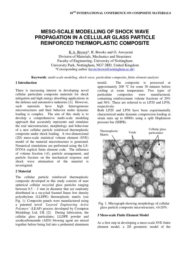
the material is investigated. 2 Material The cellular particle reinforced thermoplastic composite developed in this study consists of near spherical cellular recycled glass particles ranging between 0.5 – 2 mm in diameter that are randomly distributed in a recycled foamed linear low density polyethylene (LLDPE) thermoplastic matrix (see Fig. 1). Composite panels were manufactured using Fig. 1. Micrograph showing morphology of cellular a patented novel ‘Layered Engineering Active glass particle composite microstructure, vf=20%. Polymers’ (LEAP) process developed by Crompton Mouldings Ltd, UK [2]. During fabrication, the 3 Meso-scale Finite Element Model cellular glass particulates, LLDPE powder and azodicarbonamide (AZO) blowing agent are mixed As a first step in developing a meso-scale SVE finite together before being fed into a preheated aluminum element model, a 2D geometric model of the

  2. material microstructure was auto-generated using the A compressive shock load was applied by imposing Digimat-FE software [3]. The generation process is a specified initial velocity, U p , along the y-axis to a based on the random placement of glass particles of rigid wall at the top of the embedded boundary. A a specified size range (0.5 - 2 mm diameter) and fixed rigid wall is applied at the bottom of the volume fraction into a matrix material domain 5mm embedded boundary. x 5mm square. The cellular particles were The simulations were performed with the LS-DYNA represented as solid circles. The bond between explicit finite element code. Both the foamed particles and matrix was assumed to be perfect. thermoplastic matrix and the embedded boundary The SVE mesh and boundary conditions are shown region were modeled with the LS-DYNA elastic- in Fig. 1. Embedded cell boundary conditions were plastic foam material model, applied whereby the heterogeneous SVE is *MAT_CRUSHABLE_FOAM [5]. The cellular embedded in a homogenous outer region that has the glass particles were modeled as solid glass particles average properties of the composite material with the Johnson-Holmquist elastic-plastic damage obtained from experimental tests, similar to the model which is implement in LS-DYNA as boundary conditions developed by Mishnaevsky [4]. *MAT_JOHNSON_HOLMQUIST_CERAMICS The embedded approach avoids boundary effects on [5]. the SVE while accounting for the interaction The properties for the embedded boundary were between the SVE and the rest of the material. The obtained from experimental dynamic compression embedding region was 10mm x 10mm square. tests on the actual composite material at strain rates up to 6000/s using a split Hopkinson pressure bar (SHPB). However the properties for the composite U p constituents, i.e. the foamed LLDPE matrix and the cellular glass particles were not readily available. In order to determine the input parameters for the Embedded region matrix and glass particles, a numerical inverse calibration method was undertaken where parameters were systematically obtained by Unit cell correlating simulations with the corresponding test data. The input parameters are adjusted iteratively 5 mm 10 mm over several simulation runs until satisfactory correlation was obtained. All simulations were conducted on a HP Z600 workstation with 8 CPU (2.4 GHz) and 16 Gb RAM. y 5 mm 4 Results and discussion 4.1 Effect of volume fraction 10 mm Fig. 2 shows the random particle arrangements for x the LP20 and LP56 models that were used to investigate the effect of volume fraction on the Fig. 1. Embedded SVE mesh and boundary composite strength and shock response. Fig. 3 conditions (vf=20%). shows a comparison of experimental and simulation compression stress-strain curves for LP20 and LP56. Four-node plane-strain quadrilateral shell elements, The composites were loaded to 60% strain. As with single integration points, were used to mesh the shown in Fig. 3 there is good correlation between models. Following a mesh sensitivity study, the simulation and experimental results. In general, elements with an average length of 0.1 mm were the stress-strain response is similar to other selected. conventional cellular solids (foams) exhibiting an initial elastic response followed by yielding and

Download Presentation
Download Policy: The content available on the website is offered to you 'AS IS' for your personal information and use only. It cannot be commercialized, licensed, or distributed on other websites without prior consent from the author. To download a presentation, simply click this link. If you encounter any difficulties during the download process, it's possible that the publisher has removed the file from their server.

Recommend


More recommend