SLIDE 15 Experimental setup
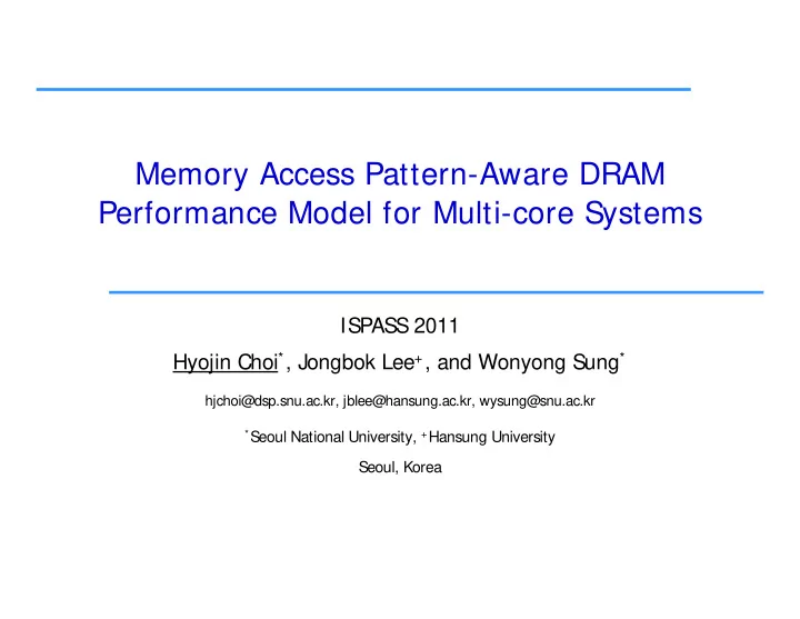
core L1I$ L1D$ gle bus
M5
Memory Controller
FR-FCFS
addr/cmd
bank 0 bank 1
cache
kernel/application description FFT.MT matrix transpose (512512) FFT.MM matrix multiplication (512512) OceanContig grid size : 258258
shared sing core L1I$ L1D$
address mapping
data bus (64 bit)
bank 7
shared L2
Cholesky input: tk23.O LUContig matrix size: 512512 Raytrace input: teapot.env FMM 2048 particles
- Architecture simulator configuration (M5)
in-order processor model (P=1,2,…,64), 2 GHz L1 cache : private separate 64 KB 2-way 64 Bytes 1 cycle L1 cache : private, separate, 64 KB, 2 way, 64 Bytes, 1 cycle L2 cache : shared, unified, 512 KB, 2-way, 64 Bytes, 20 cycles shared bus with no overhead
- Main memory subsystem
- Main memory subsystem
a cycle-accurate DRAM timing simulator extension for M5 memory controller: FR-FCFS, [row:bank:col], open-policy 2 Gb t
8 b k DDR3 800/ 1066/ 1333/ 1600 d t b idth 64 bit
2 Gbytes, 8 banks, DDR3-800/-1066/-1333/-1600, data bus width : 64 bit
- Seven multi-threaded workloads from SPLASH-2 benchmark
Multimedia Systems Lab. @ SoEE, SNU
14