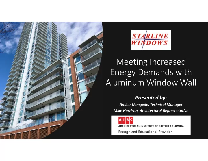
SLIDE 1 Meeting Increased Energy Demands with Aluminum Window Wall
Presented by:
Amber Mengede, Technical Manager Mike Harrison, Architectural Representative
SLIDE 2 Agenda
performance of traditional window wall systems
- Misconceptions with Step Code
- Building envelope challenges
- Thermally enhanced window wall
SLIDE 3 Thermal Performance
Wall Systems
SLIDE 4 Traditional Window Wall System Highlights
- Minimal thermal break; +/- 21mm deep
- 1” of non-continuous mineral wool in module bypass,
which also leaves the slab edge partially exposed
- Head deflection channel is partially thermally broken
with a “skip and debridge” thermal break
- Little or no insulation in other frame cavities
- Operable frames and their inserts not thermally broken
SLIDE 5 Vision Glass Areas Double Glazed
Fixed Glazing
6mm Guardian SN68 #2 / Argon / ½” WarmEdge Spacer / 4mm CLR U-value = 0.31* and SHGC of 0.33
Operable Glazing
Same glazing make-up as above U-value = 0.47* and SHGC of 0.23 *Typical overall system U-value = ~0.36 (Assumes an 80:20 ratio of fixed to operable glazing)
SLIDE 6
Opaque Wall Areas
Monolithic Spandrel Glass
6mm TEMP / Opaci-coat #2 / 3” mineral wool / GALV backpan U-value = 0.17 Effective R-value = R-6 *Based on a window wall module 48” in width
SLIDE 7
Bypass locations
Monolithic Spandrel Glass
6mm TEMP / Opaci-coat #2 / 1” mineral wool U-value = 0.29 Effective R-value = ~R-3* *Based on a window wall module 48” in width
SLIDE 8
BC Energy Step Code and the Building Envelope
SLIDE 9
Step Code: Part 3 & 9 Buildings
With massing, simpler forms are deemed to be more energy efficient in both Part 3 & Part 9. Size and placement of windows can influence a Part 3 building’s TEDI performance or a Part 9 building’s TEDI or PTL.
SLIDE 10
Step Code: Window : Wall Ratio (WWR)
BC Housing suggests selecting wall systems with a minimum R-10 effective and a WWR of 40% or less. A full “skin-wrap” with a WWR >50% is possible with aluminum window wall, if a suitable system is available from the glazing trade.
SLIDE 11
Step Code: Getting there
To help meet the performance- based approach of Step Code, the glazing trade can offer various energy values for the energy modelers to work with. Performance path trade-offs are no longer permitted as they were beforehand.
SLIDE 12 Energy Requirements
Ask for project specific, overall weighted-average energy values based on specified glazing. Ultimately, the glazing trade needs to be informed of the project’s target energy values in
SLIDE 13 Building Envelope Challenges
If the industry follows the 40% max WWR using thick insulated walls, there exists the potential for sequencing and tie-in issues that could lead to compromised building envelopes in the future, not to mention, possible costly schedule delays. ACTUAL CASE: A project with windows sitting 2 3/8” proud of the slab edge and walls that are 7” proud, due to exterior insulation. *DISCLAIMER: not the project shown
SLIDE 14 Thick Wall Design Complexity
1. Multiple trades now responsible for the building envelope versus as few as one. 2. How do you best design the flashings and sequence the membraning and waterproofing tie-ins to ensure a sound building envelope? 3. Windows are “staggered” across the elevations, as opposed to being contiguous, making this even more difficult to detail.* 4. Despite several round table discussions with the building envelope consultants & the architects, the general contractor & their client, along with the cladding trade & window manufacturer, a satisfactory flashing detail has not yet been finalized! *The details shown do not represent the true complexity of the scenario.
SLIDE 15 Pros & Cons of a Skin Wrap with Thermally Enhanced Window Wall
Skin Wrap Pros
- One trade on the building envelope
- Scheduling & sequencing easier
- Simplicity of detailing & tie-ins
- Designing for interstory drift easier
with one system
- Potential for >40% window:wall
ratio
- Unitized system built in factory-
controlled environment
Skin Wrap Cons
performance in opaque wall areas
- May be limited aesthetically in
terms of other product options for
SLIDE 16 Pros & Cons of a Punched Window Design
Punched Opening Pros
- Potentially better energy values
for the opaque areas around the windows
- Design flexibility of cladding
- ptions
Punched Opening Cons
- Multiple trades responsible for
the building envelope
- Scheduling & sequencing can be
problematic and cause delays
- Complexity of detailing & tie-ins
- Increased potential for thermal
bridging with steel studs and large flashings
SLIDE 17
Building Envelope Opportunities
Can I achieve an R-10 effective wall without using a thick wall? Can I meet Step Code now with aluminum window wall? Can I design to greater than a 50% WWR?
SLIDE 18
Thermally Enhanced Aluminum Window Wall
SLIDE 19
What was the process in designing this new thermal window wall?
Thermal performance Structural requirements Manufacturing feasibility
Shipping & installation criteria
Cost / competitively priced
SLIDE 20 Thermally Enhanced Window Wall What should you look for…
Larger, continuous thermal breaks in all components including the head deflection channel, seismic jambs, vent inserts and
More insulation in the various frame cavities than seen before in traditional window wall systems Insulation applied “continuously” on the face of the slab edge
SLIDE 21 …and what can you expect?
Overall thermal performance is improved up to 100% compared to traditional window wall systems.
U-fen as low as 0.165*
(Fixed / non-operable glazing)
*Triple glazed with soft coat low-E
- n surface #2 & #4 with hard coat
low-E on surface #6.
SLIDE 22
Multi- chamber Dual-strut Polyamide Thermal Break
Using a larger thermal break improves energy performance, however it can allow for increased convection and decrease thermal resistance By adding fins to this larger thermal break, convection within the cavity is reduced, resulting in overall improved thermal performance Polyamide is superior to PVC for thermal breaks as polyamide is structural in nature with its glass reinforcing fibres
SLIDE 23 Key insulating features…
- Larger (41mm) multi-chamber, dual-strut polyamide
thermal break in all window profiles
- 2 ½” of continuous mineral wool at face of slab edge
- Head Deflection Channel is now completely thermally
broken with a similar multi-chamber, dual-strut polyamide thermal break vs “skip and debridge”
- Increased amount of insulation in various frame cavities,
including 4 ½” of R-19 mineral wool in the spandrel backpan
- Intermittent shims between the perimeter frames & the
structure provide an additional thermal break and addresses concrete tolerances at the same time
SLIDE 24
Additional Insulating Features
Mineral wool insulation in the cavities of all couplers, seismic jambs and the aluminum corner posts (not shown), as well as the larger, 41 mm thermal break in the seismic compensation jamb channel.
SLIDE 25 Slab Edge Positioning
- The new system is 6 1/8” deep overall, however, the
nominal support on the slab does not need to be any greater than traditional systems.
- Designed for 1 7/8” nominal support using a T-angle
allowing for the 2 ½” of mineral wool blanketing the slab edge continuously.
- No impact on membrane detailing
- Effective R-value at slab edge increases to ~R-9 as a result
SLIDE 26 Why can the system sit so far outside the structure?
Structural polyamide thermal break with glass reinforced fibres
The hems of the aluminum profiles are knurled and then the thermal break is crimped in place Rigorous QA/QC process includes slippage failure shear tests of all profiles, ensuring structural integrity Structurally simulated and modelled in Ansys Experience with installing cantilevered 6" deep window wall systems
SLIDE 27
Energy Values for Thermally Enhanced Window Wall
SLIDE 28 2D Energy Values Double Glazed Fenestration Values
(incl. frame, mullions, sash w/ vision glass) Soft Coat Low-e #2 / CLEAR w/Argon, WarmEdge Spacer Ufen = 0.30* and SHGC of 0.32 Soft Coat Low-e #2 / Hard Coat #4, Argon, WarmEdge Ufen = 0.26 and SHGC of 0.32 *Traditional system has a Ufen of 0.36 by comparison (Assumes an 80:20 ratio of fixed to operable glazing)
SLIDE 29 2D Energy Values Triple glazed Fenestration Values
(incl. frame, mullions, sash w/ vision glass) Single Low-e (Soft coat) Soft Coat #2 / CLEAR / CLEAR w/Argon, WarmEdge Spacer Ufen = 0.25 and SHGC of 0.30 Double Low-e (Soft & Hard coat) Soft Coat #2 / CLEAR / Hard Coat #6 w/Argon, WarmEdge Ufen = 0.22 and SHGC of 0.29 (Assumes an 80:20 ratio of fixed to operable glazing)
SLIDE 30 2D Energy Values Triple glazed Fenestration Values
(incl. frame, mullions, sash w/ vision glass) Double Soft Coat Soft Coat Low-e #2 and #4 / CLEAR Argon, WarmEdge Spacer = Ufen of 0.21 and SHGC of 0.26 Double Soft Coat & single Hard Coat Soft Coat Low-e #2 and #4 / Hard Coat #6, Argon, WarmEdge = Ufen of 0.18 and SHGC of 0.25 (Assumes an 80:20 ratio of fixed to operable glazing)
SLIDE 31 2D Energy Values Bypass
Monolithic spandrel glass: ~R-8* Shadowbox spandrel glass: ~R-9*
*Traditional system averages approx. R-3 at the slab edge.
SLIDE 32 2D Energy Values Opaque Walls
Monolithic Spandrel Glass: ~R-11* Shadowbox Spandrel Glass: ~R-12* Opaque energy values can be further improved using insulating blanket in lieu of mineral wool resulting in ~R-18.2 effective.
*Traditional system averages R-6 at opaque walls (Based on a test size of 47" x 59“)
SLIDE 33
How were these energy values determined?
2D modelling by in house certified NFRC Specialist for spandrel and vision areas using NFRC methodology City of Vancouver’s Energy STEP Code modelling guidelines were followed
SLIDE 34
Besides 2D modelling, 3D modelling was performed by a third party
City of Vancouver’s Energy STEP Code modelling guidelines has seven different possible methods to be used for modelling spandrel. Both 2D & 3D are one of the allowable methodologies Would make it simpler to streamline the requirements (similar concept to NFRC) so there can be apple-to-apple comparisons. Having seven different methods leads to inconsistent results between manufacturers.
NFRC is currently working on implementing a standard for modelling spandrel
SLIDE 35 3D Thermal Modelling Results
Source: Morrison Hershfield Thermal Analysis Report (#180508701); September 9, 2019.
SLIDE 36 Modelling Geometry for Thermal Wall
Upstand spandrel section of 28” plus 8” bypass
And
Full height, floor to floor spandrel with bypass
A1
SLIDE 37 Slide 36 A1
Author, 2019-04-08
SLIDE 38 Thermal Wall Overall Temperature Profile
Full height, floor to floor spandrel with 2” of inboard insulation.
(Presented as a temperature index between 0 and 1)
Source: Morrison Hershfield Thermal Analysis Report #180508701 dated September 9, 2019.
SLIDE 39 Slab Edge Temperature Profile Comparison
New (9600 Series) Thermal Wall Traditional (9003 Series) Window Wall
2 ½” continuous mineral wool at the slab edge; no insulation in stud wall behind the spandrel 1” continuous mineral wool at the slab edge; 3” medium density spray foam in stud wall behind the spandrel
SLIDE 40 3D vs 2D for Thermal Modelling
3D modelling offers a high level of accuracy as it directly models the geometry and heat flow as a complete system of connected components 2D modelling has been traditionally what window manufacturers have been using for years. The biggest difference between 3D & 2D is the surface temperature and evaluating the condensation risk Surface temperatures for 2D are averages at best due to lateral heat transfer from the aluminum framing and metal back pans in 3 dimensions Although ideal to use the most accurate 3D method for project- specific spandrel sizes, it is not feasible due to the cost, time and limited availability of personnel qualified in 3D modelling
SLIDE 41 Energy Value Results 3D vs 2D
Our in-house certified NFRC simulator 2D modelled the same module sizes as were used in Morrison Hershfield’s thermal analysis report, where 3D modelling was used. The 3D modelling report verified our in-house 2D modelled results, where
- urs were deemed conservative by
comparison.
SLIDE 42 Accounting for Thermal Bridging… as specified by the BC Energy Step Code
Accounting for thermal bridging
- f installation components has
typically been done by the BEC’s to date It typically falls within their scope of work versus the manufacturers’ and they have the capability to do so
SLIDE 43 Thermal Bridging
Components
All fasteners are inboard of the thermal breaks Sill flashings are attached outboard
- f the thermal break to an exterior,
downward leg
Use of pan flashings is discouraged wherever possible to further mitigate thermal transfer
SLIDE 44 Summary
- Traditional aluminum window wall
systems are thermally challenged.
- Misconceptions with the Step
Code is suggesting window-wall- ratios need to be much lower than we’re used to seeing in BC.
- Building envelope detailing and
sequencing may prove difficult to resolve with multiple trades.
SLIDE 45
The future…
With a thermally enhanced aluminum window wall system, building envelope designs may not have to change as drastically as first thought to meet increased energy demands and the BC Energy Step Code.
SLIDE 46
Thank you!...and please contact us for technical and design inquiries.
architectural@starlinewindows.com technical@starlinewindows.com
604-882-5100