SLIDE 1
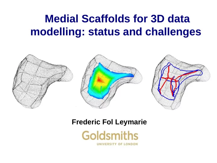
Medial Scaffolds for 3D data modelling: status and challenges
Frederic Fol Leymarie
SLIDE 2
Outline
Background Method and some algorithmic details Applications
SLIDE 3 Shape representation: From the Medial Axis to the Medial Scaffold
Wave propagation Blum, Voronoi, Turing, et al. Maximal disks Blum, Wolter, Leyton, Kimia, Giblin, et al.
SLIDE 4
Context: 1st reconstruct a surface mesh from unorganized points, with a “minimal” set of assumptions: the samples are nearby a “possible” surface (thick volumetric traces not considered here). Benefit: reconstruction across many types of surfaces. Study 3D shape with minimal assumptions
SLIDE 5
Context: 1st reconstruct a surface mesh from unorganized points, with a “minimal” set of assumptions: the samples are nearby a “possible” surface (thick volumetric traces not considered here). Benefit: reconstruction across many types of surfaces. Study 3D shape with minimal assumptions
SLIDE 6
Context: 1st reconstruct a surface mesh from unorganized points, with a “minimal” set of assumptions: the samples are nearby a “possible” surface (thick volumetric traces not considered here). Benefit: reconstruction across many types of surfaces. Study 3D shape with minimal assumptions
SLIDE 7 Study shape with minimal assumptions
To find a general approach, applicable to various topologies, without assuming strong input constraints, e.g.:
– No surface normal information. – Unknown topology (with boundary, for a solid, with holes, non-orientable). – No a priori surface smoothness assumptions. – Practical sampling condition: non-uniformity, with varying degrees of noise. – Practical large input size (> millions of points).
SLIDE 8
Outline
Background Method and some algorithmic details Applications
SLIDE 9 How: Overview of Our Approach (2D)
Not many clues from the assumed loose input constraints.
- Work on the shape itself to recover the sampling process.
Key ideas:
- Relate the sampled shape with the underlying (unknown) surface by
a sequence of shape deformations (growing from samples).
- Represent (2D) shapes by their medial “shock graphs”. [Kimia et al.]
- Handle shock transitions across different shock topologies
to recover gaps.
SLIDE 10 How: Sampling / Meshing as Deformations
We consider the removing of a patch from the surface as a Gap Transform. 2D:
Schematic view of sampling: infinitesimal holes grows, remaining are the samples.
3D:
SLIDE 11 How: Sampling / Meshing as Deformations
Special case where input consists only of points (in 3D), then the Medial Scaffold consists of only: A1
2 Sheets, A1 3 Curves, A1 4 Vertices.
A1
2 Sheet
A1
4 Vertex
A1
3 Curve
SLIDE 12 How: Sampling / Meshing as Deformations
CVIU 2009, Chang, Fol Leymarie, Kimia.
SLIDE 13 How: Medial Scaffolds for 3D Shapes
A graph structure for the 3D Medial Axis
Classify shock points into 5 general types, and organized into a hyper-graph form [Giblin&Kimia PAMI’04, Leymarie&Kimia PAMI'07]:
– Shock Sheet: A1
2
– Shock Curves: A1
3 (Axial), A3 (Rib)
– Shock Vertices: A1
4, A1A3
Ak
n: contact (max. ball) at n distinct
points, each with k+1 degree of contact.
SLIDE 14
How: Medial Scaffolds for 3D Shapes
A graph structure for the 3D Medial Axis
SLIDE 15
How: Medial Scaffolds for 3D Shapes
A graph structure for the 3D Medial Axis
SLIDE 16
How: Medial Scaffolds for 3D Shapes
A graph structure for the 3D Medial Axis
SLIDE 17
How: Medial Scaffolds for 3D Shapes
A graph structure for the 3D Medial Axis
SLIDE 18 Transitions of the 3D graph structure
Study the topological events of the graph structure under perturbations perturbations and shape deformations shape deformations. Singularity theory Singularity theory (Arnold et al., since the 1990's):
In 3D, 26 topologically different perestroikas of linear shock waves.
“Perestroikas of shocks and singularities of minimum functions”
SLIDE 19 Transitions of the 3D graph structure
Study the topological events of the graph structure under perturbations perturbations and shape deformations shape deformations.
Transitions of the MA (Giblin, Kimia, Pollit, PAMI 2009):
Under a 1-parameter family of deformations, only seven transitions
seven transitions are relevant.
SLIDE 20 Transitions of the 3D graph structure
Study the topological events of the graph structure under perturbations perturbations and shape deformations shape deformations.
Transitions of the MA:
Under a 1-parameter family of deformations, only seven transitions
seven transitions are relevant. (protrusion-like, Leymarie, PhD, 2002) A1A3-I
SLIDE 21 Transitions of the 3D graph structure
Study the topological events of the graph structure under perturbations perturbations and shape deformations shape deformations.
A1A3-I A1
5
A1
4
A5 A1A3-II A1
2A3-I A1 2A3-II
twisted parabolic gutter parabolic gutter with a bump squeezed tube parallel plane with a bump
Total of 11 cases for regularization across transitions (M.C. Chang et al.)
SLIDE 22 Transitions of the 3D graph structure
Study the topological events of the graph structure under perturbations perturbations and shape deformations shape deformations.
Towards surface regularisations via transitions (Leymarie, Giblin, Kimia, 2004)
SLIDE 23 Transitions of the 3D graph structure
Study the topological events of the graph structure under perturbations perturbations and shape deformations shape deformations.
Capture transitions via geodesy on MA (Chang, Kimia, Leymarie, on-going)
SLIDE 24
Outline
Background Method and some algorithmic details Applications
SLIDE 25 How: Organise/Order Deformations (2D)
Deformation in shape space B A NB: A & B share object symmetries. Symmetries due to the sampling need to be identified.
SLIDE 26 How: Organise/Order Deformations (3D)
- Recover a mesh (connectivity) structure by using Medial Axis transitions
modelled via the Medial Scaffold (MS).
– Meshing as shape deformations in the ‘shape space’.
- The Medial Scaffold of a point cloud includes both the symmetries due to
sampling and the original object symmetries.
– Rank order Medial Scaffold edits (gap transforms) to “segregate” and to simulate the recovery of sampling. Shock Segregation [Leymarie, PhD’03], Surface reconstruction [CVIU'09]
Meshed Surface + Organized MA Object symmetry Sampling recovery
SLIDE 27 Algorithmic Method
- Consider Gap Transforms on all A1
3 shock curves in a
ranked-order fashion:
– best-first (greedy) with error recovery.
– Likelihood that a shock curve (triangle) represents a surface patch. – Consistency in the local context (neighboring triangles). – Allowable (local surface patch) topology. 3 Types of A1
3 shock curves (dual Delaunay triangles):
Represented in the MS by “singular shock points” (A1
3-2)
(unlikely to be correct candidate)
A1
3 shock curve
Three A1
2 shock sheets
A1
3-2
G1 G2 G0 A1
3-2 singular
shock point G1 G2 G0 G3 G1 G2 G0
Type I Type II Type III
SLIDE 28 Algorithmic Method
How we order gap transforms:
- Favor small “compact” triangles.
- Favor recovery in “nice” (simple) areas, e.g.,
away from ridges, corners, necks.
- Favor simple local continuity (similar orientation).
- Favor simple local topologies (2D manifold).
- BUT: allow for error recovery!
SLIDE 29 Ranking Isolated Shock Curves (Triangles)
R: minimum shock radius dmax: maximum expected triangle, estimated from dmed
Triangle geometry:
Cost: favors small compact triangles
with large shock radius R.
(Heron’s formula) (Compactness, Gueziec’s formula, 0<C<1) The side of smaller shock radius is more salient.
Surface meshed from confident regions toward the sharp ridge region.
R R
unbounded
SLIDE 30 Cost Reflecting Local Context & Topology
Cost to reflect smooth continuity of edge-adjacent triangles:
Point data courtesy of Ohtake et al.
Typology of triangles sharing an edge: Typology of mesh vertex topology
SLIDE 31 Strategy in the Greedy Meshing Process
Problem: Local ambiguous decisions errors. Solutions:
- Multi-pass greedy iterations
First construct confident surface triangles without ambiguities.
- Postpone ambiguous decisions
– Delay related candidate Gap Transforms close in rank, until additional supportive triangles (built in vicinity) are available. – Delay potential topology violations.
– For each Gap Transform, re-evaluate cost of both related neighboring (already built) & candidate triangles. – If cost of any existing triangle exceeds top candidate, undo its Gap Transform.
Queue of
SLIDE 32 Dealing with sampling quality
Input of non-uniform and low-density sampling: Response to additive noise:
50% 100% 150%
SLIDE 33
Outline
Background Method and some algorithmic details Applications
SLIDE 34
From Fine to Coarse Scales
SLIDE 35
Bone shape study
SLIDE 36
3D Tubular & Branching Shapes
SLIDE 37
3D Tubular & Branching Shapes
SLIDE 38
3D Tubular & Branching Shapes
SLIDE 39
3D Convoluted Shapes: Brains
SLIDE 40
3D Shape Matching/Registration
SLIDE 41 3D Shape in Molecular biochemistry
FoldSynth project: Docking www.foldsynth.com
SLIDE 42
Outline
Background Method and some algorithmic details Applications … Conclusions
SLIDE 43 Next: 3D Shape Deformation
- [Kimia et al.] represent shape as a member of an equivalent class
(‘shape cell’), each defined as the set of shapes sharing a common shock graph (in 3D, Medial Scaffold) topology.
- Link this to Information Models: incorporation of human expert
knowledge; e.g. in building taxonomies.
- Statistical analysis; definition of classes; distribution of features.
- Combine exterior with interior scaffolds.
SLIDE 44
SLIDE 45 Other open issues:
- Combine or study relations with other existing main
shape representations based on propagations: Voronoi, Morse/Reeb, flow complex, 3D Curve skeletons
- Interactions between 2D and 3D inputs : visual
inputs/snapshots (2D) versus 3D percepts : no trivial correspondence between 2D and 3D medial representations (including Voronoi)
SLIDE 46 Other open issues:
- Medial representations directly from intensity fields :
images, video, 3D medical volumetric data : e.g. work of Kovacs et al. on robust symmetries.
- related: using a probabilistic framework or robust
measures to deal with noisy inputs or sampling obtained in sausages (neighborhoods) rather than precisely on an outline/surface
- Complexity, proofs of convergences for realistic data
(not too smooth).