Mass Storage & IO Positioning time ( random-access time ) is - - PDF document

mass storage io
SMART_READER_LITE
LIVE PREVIEW

Mass Storage & IO Positioning time ( random-access time ) is - - PDF document

CSC 4103 - Operating Systems Overview of Mass Storage Structure Spring 2008 Magnetic disks provide bulk of secondary storage of modern computers Drives rotate at 60 to 200 times per second Lecture - XVIII Transfer rate is rate at


slide-1
SLIDE 1

1

CSC 4103 - Operating Systems Spring 2008

Tevfik Koar

Louisiana State University

April 8th, 2008

Lecture - XVIII

Mass Storage & IO

Overview of Mass Storage Structure

  • Magnetic disks provide bulk of secondary storage of modern computers

– Drives rotate at 60 to 200 times per second – Transfer rate is rate at which data flow between drive and computer – Positioning time (random-access time) is time to move disk arm to desired cylinder (seek time) and time for desired sector to rotate under the disk head (rotational latency) – Head crash results from disk head making contact with the disk surface

  • That’s bad
  • Disks can be removable
  • Drive attached to computer via I/O bus

– Busses vary, including EIDE, ATA, SATA, USB, Fibre Channel, SCSI – Host controller in computer uses bus to talk to disk controller built into drive

  • r storage array

Overview of Mass Storage Structure (Cont.)

  • Magnetic tape

– Was early secondary-storage medium – Relatively permanent and holds large quantities of data – Access time slow – Random access ~1000 times slower than disk – Mainly used for backup, storage of infrequently-used data, transfer medium between systems – Kept in spool and wound or rewound past read-write head – Once data under head, transfer rates comparable to disk – Hundreds of GB typical storage – Common technologies are 4mm, 8mm, 19mm, LTO-2 and SDLT

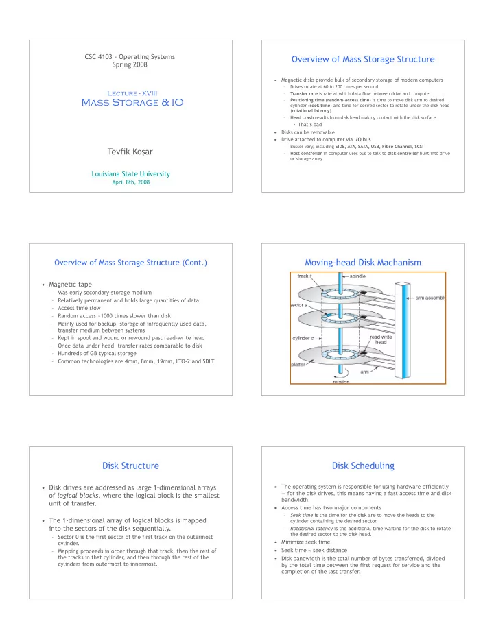
Moving-head Disk Machanism Disk Structure

  • Disk drives are addressed as large 1-dimensional arrays
  • f logical blocks, where the logical block is the smallest

unit of transfer.

  • The 1-dimensional array of logical blocks is mapped

into the sectors of the disk sequentially.

– Sector 0 is the first sector of the first track on the outermost cylinder. – Mapping proceeds in order through that track, then the rest of the tracks in that cylinder, and then through the rest of the cylinders from outermost to innermost.

Disk Scheduling

  • The operating system is responsible for using hardware efficiently

— for the disk drives, this means having a fast access time and disk bandwidth.

  • Access time has two major components

– Seek time is the time for the disk are to move the heads to the cylinder containing the desired sector. – Rotational latency is the additional time waiting for the disk to rotate the desired sector to the disk head.

  • Minimize seek time
  • Seek time seek distance
  • Disk bandwidth is the total number of bytes transferred, divided

by the total time between the first request for service and the completion of the last transfer.

slide-2
SLIDE 2

Disk Scheduling (Cont.)

  • Several algorithms exist to schedule the servicing of

disk I/O requests.

  • We illustrate them with a request queue (0-199).

98, 183, 37, 122, 14, 124, 65, 67 Head pointer 53

FCFS

Illustration shows total head movement of 640 cylinders.

SSTF

  • SSTF: Shortest Seek Time First Algorithm
  • Selects the request with the minimum seek time from

the current head position.

  • SSTF scheduling is a form of SJF scheduling; may cause

starvation of some requests.

  • Illustration shows total head movement of 236

cylinders.

SSTF (Cont.) SCAN

  • The disk arm starts at one end of the disk, and moves

toward the other end, servicing requests until it gets to the other end of the disk, where the head movement is reversed and servicing continues.

  • Sometimes called the elevator algorithm.
  • Illustration shows total head movement of 208

cylinders.

SCAN (Cont.)

slide-3
SLIDE 3

C-SCAN

  • Provides a more uniform wait time than SCAN.
  • The head moves from one end of the disk to the other.

servicing requests as it goes. When it reaches the other end, however, it immediately returns to the beginning

  • f the disk, without servicing any requests on the

return trip.

  • Treats the cylinders as a circular list that wraps around

from the last cylinder to the first one.

C-SCAN (Cont.) C-LOOK

  • Version of C-SCAN
  • Arm only goes as far as the last request in each

direction, then reverses direction immediately, without first going all the way to the end of the disk.

C-LOOK (Cont.) Selecting a Disk-Scheduling Algorithm

  • SSTF is common since increases performance over FCF

, but may cause starvation.

  • SCAN and C-SCAN perform better for systems that place a heavy

load on the disk, prevent starvation.

  • LOOK and C-LOOK optimize SCAN and S-SCAN further.
  • Performance depends on the number and types of requests.
  • Requests for disk service can be influenced by the file-allocation

method.

  • The disk-scheduling algorithm should be written as a separate

module of the operating system, allowing it to be replaced with a different algorithm if necessary.

  • Either SSTF or LOOK is a reasonable choice for the default

algorithm.

18

Acknowledgements

  • “Operating Systems Concepts” book and supplementary

material by A. Silberschatz, P . Galvin and G. Gagne

  • “Operating Systems: Internals and Design Principles”

book and supplementary material by W. Stallings

  • “Modern Operating Systems” book and supplementary

material by A. Tanenbaum

  • R. Doursat and M. Yuksel from UNR