
SLIDE 1
Bearing Capacity of Rocks Intact Rock Mass Intact Rock Mass A rock - - PowerPoint PPT Presentation
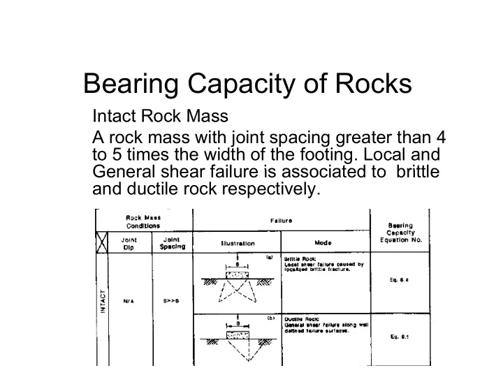
Bearing Capacity of Rocks Intact Rock Mass Intact Rock Mass A rock mass with joint spacing greater than 4 to 5 times the width of the footing. Local and General shear failure is associated to brittle General shear failure is associated to
Foundations on Fractured Rock Formation
30
MPa)
Note: Use maximum qa < q u where qu = compressive strength
20 25
ress qa (M
where qu compressive strength
15
earing Str
) 130 / ( 1 ) 16 / ( 1 ) ( RQD RQD MPa q ALLOWABLE − + ≈
NOTE: 1 MPa = 10 tsf
5 10
Peck, et al. (1974)
NOTE: 1 MPa = 10 tsf 10 20 30 40 50 60 70 80 90 100
Allo
( ) Approximation
Rock Quality Designation, RQD
In case of rock mass with favorable discontinuities, the net allowable bearing pressure may be estimated from: qa = qc * Nj Where qc = average uniaxial compressive strength of rock cores Where qc average uniaxial compressive strength of rock cores Nj = empirical coefficient depending on the spacing of the discontinuities
δ = thickness of discontinuity δ = thickness of discontinuity S = spacing of discontinuities B = width of footing The above relationship is valid for a rock mass with spacing of continuities > 0.3 m, δ < 10 mm (15 mm if filled with soil) and B >0 3 m B >0.3 m.
The allowable bearing capacity of socketed piles is given by: qa = qc * Nj * Nd Where Where Nd = 0.8 + 0.2 h/d h = depth of socket in rock d = diameter of socket
f l d f a
Where qa = allowable bearing pressure in t/m2 Pl = limit pressure determined by the Pressuremeter in t/m2 γ Df = overburden pressure in t/m2