LOW-VELOCITY IMPACT BEHAVIORS OF A DEFORMABLE THIN METALLIC SANDWICH - - PDF document

low velocity impact behaviors of a deformable thin
SMART_READER_LITE
LIVE PREVIEW

LOW-VELOCITY IMPACT BEHAVIORS OF A DEFORMABLE THIN METALLIC SANDWICH - - PDF document

18 TH INTERNATIONAL CONFERENCE ON COMPOSITE MATERIALS LOW-VELOCITY IMPACT BEHAVIORS OF A DEFORMABLE THIN METALLIC SANDWICH PLATE D. G. Ahn 1 *, G. H. Nam 2 , S. H. Kim 1 , G. Y. Han 1 , D. Y. Seoung 3 , D. Y. Yang 3 1 Dept. of Mech. Eng., Chosun


slide-1
SLIDE 1

18TH INTERNATIONAL CONFERENCE ON COMPOSITE MATERIALS

1 Introduction Transport vehicle industries have been faced with demands on the weight saving to improve the energy efficiency [1]. In addition, the demands on the improved strength, stiffness and crashworthiness of structural components have been increased to enhance the safety of the transport vehicles [1]. As an alternative of the conflict demands, a lightweight metallic sandwich plate with three-dimensional inner structures has been developed [2,3]. Despite of advantageous characteristics

  • f

the metallic lightweight sandwich plate, such as a superb specific stiffness and distinguished crashworthiness, it was difficult to apply the sandwich plate to components

  • f the transport vehicle which were manufactured

from the forming process [4]. Hence, Yang et al. developed a deformable thin metallic sandwich plate with three types of the metallic inner structures, including bi-axial corrugated, dimple and sheared dimple structures, to improve the formability and to apply the sandwich plate to components of the transport vehicle [5,6]. Seong et al. investigated into the quasi-static bending behaviors of the deformable thin metallic sandwich plate [5,6]. However, the examination of the behavior of the deformable thin metallic sandwich plate under low-velocity impact loading was additionally needed to apply the sandwich plate to transport vehicles. The objective

  • f this paper is to investigate into impact behaviors
  • f a deformable thin metallic sandwich plate with

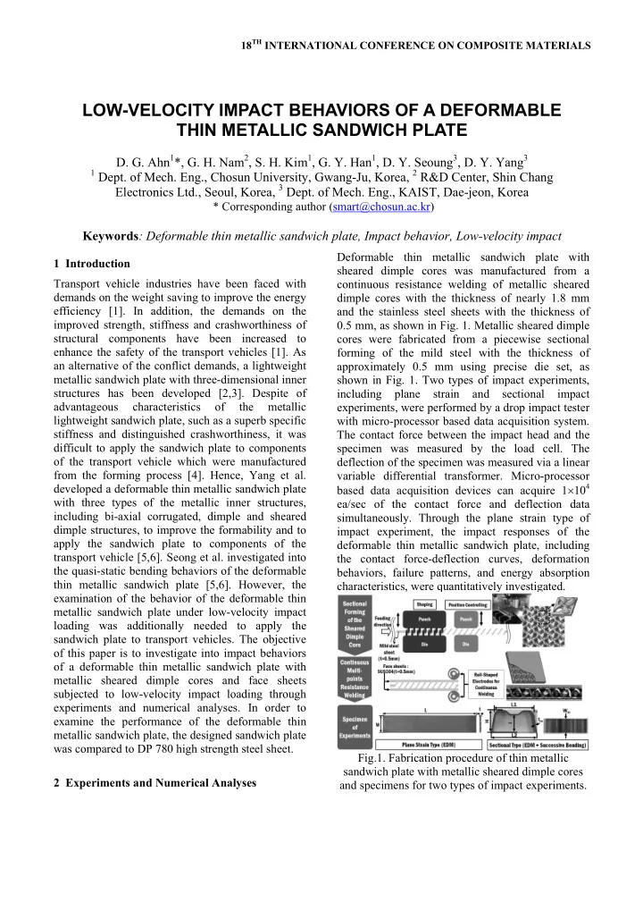
metallic sheared dimple cores and face sheets subjected to low-velocity impact loading through experiments and numerical analyses. In order to examine the performance of the deformable thin metallic sandwich plate, the designed sandwich plate was compared to DP 780 high strength steel sheet. 2 Experiments and Numerical Analyses Deformable thin metallic sandwich plate with sheared dimple cores was manufactured from a continuous resistance welding of metallic sheared dimple cores with the thickness of nearly 1.8 mm and the stainless steel sheets with the thickness of 0.5 mm, as shown in Fig. 1. Metallic sheared dimple cores were fabricated from a piecewise sectional forming of the mild steel with the thickness of approximately 0.5 mm using precise die set, as shown in Fig. 1. Two types of impact experiments, including plane strain and sectional impact experiments, were performed by a drop impact tester with micro-processor based data acquisition system. The contact force between the impact head and the specimen was measured by the load cell. The deflection of the specimen was measured via a linear variable differential transformer. Micro-processor based data acquisition devices can acquire 1104 ea/sec of the contact force and deflection data

  • simultaneously. Through the plane strain type of

impact experiment, the impact responses of the deformable thin metallic sandwich plate, including the contact force-deflection curves, deformation behaviors, failure patterns, and energy absorption characteristics, were quantitatively investigated. Fig.1. Fabrication procedure of thin metallic sandwich plate with metallic sheared dimple cores and specimens for two types of impact experiments.

LOW-VELOCITY IMPACT BEHAVIORS OF A DEFORMABLE THIN METALLIC SANDWICH PLATE

  • D. G. Ahn1*, G. H. Nam2, S. H. Kim1, G. Y. Han1, D. Y. Seoung3, D. Y. Yang3

1 Dept. of Mech. Eng., Chosun University, Gwang-Ju, Korea, 2 R&D Center, Shin Chang

Electronics Ltd., Seoul, Korea, 3 Dept. of Mech. Eng., KAIST, Dae-jeon, Korea * Corresponding author (smart@chosun.ac.kr) Keywords: Deformable thin metallic sandwich plate, Impact behavior, Low-velocity impact

slide-2
SLIDE 2

The absorbed energy by the specimen was estimated by the direct integration of the contact force- deflection curves. The relative impact performance

  • f the deformable thin metallic sandwich plate to DP

780 high strength steel, which was used as the material of the bumper back beam of an automotive, was examined via the plane strain and sectional impact experiments. Fig. 2 illustrates the concept of the plane strain and sectional impact experiments. Specimens of the plane strain impact experiment were fabricated from the electro discharge machining (EDM), as shown in Fig. 1. Specimens of the sectional impact experiment were created by the EDM and a successive bending process, as shown in

  • Fig. 1. Tables 1 and 2 show specimen dimensions

for two types of impact experiments. In the impact experiments, the applied impact energy and the impact velocity lay in ranges of 43.9-76.8 J and 2.8- 3.5 m/sec, respectively. Nose diameter of the impact head for the plane strain test was 30 mm. Dimensions of the impact head for the sectional test was 130 mm  50 mm. Fig.2. Concepts of two types of impact experiments. Table 1 Specimen dimensions (Plane strain type). Specimen L (mm) W (mm) t (mm) m (g) Sandwich 200.0 40.0 2.8 91.5 DP780 200.0 40.0 1.8 111.9 Table 2 Specimen dimensions (Sectional type). Specimen Sandwich DP780 L1 (mm) 92.2 90.1 L2 (mm) 103.7 107.8 tm (mm) 2.8 1.7 H (mm) 52.0 51.5 I (mm) 42.3 42.1 Wm (mm) 30.1 29.8 m (g) 63.5 70.9 In order to examine deformation and failure characteristics of the face sheets and cores as well as the energy absorption mechanism of the deformable thin metallic sandwich plate during the plane strain type of impact loading were simulated using a commercial code ABAQUS V6.5 Explicit. The impact head and the fixture were assumed as analytical rigid surfaces, as shown in Fig. 3. Face sheets and sheared dimple cores were represented by 27,843 solid elements and 65,587 nodes. Hexahedron elements of 4 layers and tetrahedron elements of 3 layers were employed for modeling of the face sheets and the sheared dimple cores. The effective length of the critical element, the initial time increment of the explicit time integration and the damping coefficient for the impact analysis were chosen as 0.05 mm, 1.9510-8 sec and 1.9010-8 Nsec/mm, respectively. High speed tensile tests were performed to obtain stress-strain relationships with the effects of strain rate. Piecewise linear model was adopted to apply the results of high speed tensile tests to the impact analysis. Fig.3. Finite element model of the impact analysis. 3 Results and Discussions 3.1 Deformation Behaviors, Failure Patterns and Energy Absorption Characteristics

  • Fig. 4 shows the influence of the impact energy on

the contact force-deflection curves. In the Fig. 4, it was observed that the contact force-deflection curves fluctuate. This maybe ascribed to the fact that a successive change of the contact area between the impact head and the specimen induced a successive local wrinkling of the face sheet, as shown in Fig. 5. In the Fig. 4, it was found that the restitution of the specimen hardly occurs when the impact energy is more than 65.9 J. In addition, it was noted that the fluctuation cycle of the contact force-deflection curve augments when the impact energy increases.

slide-3
SLIDE 3

3 LOW-VELOCITY IMPACT BEHAVIORS OF A DEFORMABLE THIN METALLIC SANDWICH PLATE

Fig.4. Influence of the impact energy (E) on the contact force-deflection curves. Fig.5. Deformed shapes and failure patterns for different impact energies.

  • Fig. 4 showed that the contact force increases when

the impact energy augments. This was due to the fact that the increased impact energy augments the strain rate of the specimen in the impacted region and the dynamic strength of the specimen is subsequently enhanced [7]. From the Figs. 4 and 5, it was noted that the thin metallic sandwich plate can deform to nearly 76 mm of stroke without the fracture of the specimen. Through the observation of the deformed shapes, it was noted that the dominant failure pattern is a local wrinkling of the face sheets, as shown in Fig. 5.

  • Fig. 6 shows the effects of impact energy on the

specific absorbed energy. The figure showed that the specific absorbed energy linearly increases when the impact energy is less than 60.4 J, while the specific absorbed energy is nearly identical when the impact energy exceeds 60.4 J. From this result, it was noted that the critical impact energy for the case of the plane strain impact loading is 60.4 J. Fig. 7 shows Fig.6. Effects of the impact energy on the specific absorbed energy. Fig.7. Micro-CT images of the cores in the vicinity

  • f the impacted region for different impact energies.

the Micro-CT images of the cores in the vicinity of the impact regions. The figure showed that an excessive shear deformation of the cores, which can be measured by the rotation angle of core relative to the face-sheet [4], occurs when the impact energy is 65.9 J. Through the investigation of the Micro-CT images and the specific absorbed energy-impact energy curves, it was noted that the excessive shear deformation of the cores decreases the specific absorbed energy by the thin metallic sandwich plate due to the reduction of the second moment of the inertia of the sandwich plate. In addition, it was found that the excessive shear deformation of the core is initiated from the critical impact energy. From the Figs. 5 and 7, it was observed that local wrinkling of the face sheets is induced by depression and shear deformation of the cores. The results of numerical analyses were compared to those of experiments. Fig. 8 showed that the deformed shape of numerical model in the vicinity

  • f the impacted region is similar to that of
  • experiment. The results of comparison showed that

numerical errors for maximum contact force and deflection are less than 1 %. From these results, it was shown that the numerical model can properly simulate the deformation behavior and impact responses of the thin metallic sandwich plate during the plane strain impact loading.

slide-4
SLIDE 4

Fig.8. Comparison of the results of numerical analyses with those of experiments (Impact energy = 43.9 J).

  • Fig. 9 shows the deformed shapes of a deformable

thin metallic sandwich plate for different impact

  • times. The figure showed that the compression of the

top face sheet by the impact head give rise to the depression of the cores. The shear deformation of the cores was induced by the difference of normal deformations between top and bottom face sheets. The shear deformation of cores augmented when the deflection of the thin sandwich plate increased. In a large deflection region of the thin sandwich plate, a significant densification and an excessive shear deformation of the cores took place in the vicinity of the third to the seventh core from the center of the specimen, as shown in Fig. 9. The number of the significantly depressed and excessively sheared cores increased when the impact energy augmented, as shown in Figs. 10 and 11. Through the investigation of the specimen deformation, it was

  • bserved that a local wrinkling of the face sheets is

induced by the depression and the shear deformation

  • f the cores. Fig. 10 shows the principal stress-

impact time curves for different impact energies and

  • locations. In the figure, it was observed that the

principal stress in welding region between the top face sheet and the core, which is indicated as “the measure location 3”, abruptly increases when the impact time ranges from 0.015 sec to 0.02 sec. Through the investigation of the deformation, it was noted that the abrupt increase of the principal stress in welding region is induced by a large deformation

  • f the welding region as the significant densification
  • f core and the excessive local wrinkling of the face

sheet are initiated. Fig. 10 showed that the principal stress of the location 3 lies in the range of 81.7- 92.6 % of that of the location 1 when the impact energy is 65.9 J and impact time is over 0.0168 sec. Fig.9. Deformed shape of thin metallic sandwich plate during impact loading (Impact energy = 43.9 J). Fig.10. Principal stress-impact time curves for different impact energies and locations. From this result, it was noted that the minimum difference of principal stress between top and bottom surfaces is less than 10 % when the impact energy is greater than the critical impact energy.

  • Figs. 9, 10 and 11 showed that an evident thinning
  • f the bottom face sheet takes place in the region of

a significant densification and an excessive shear deformation of the core. These figures also showed that an excessive thinning of the bottom face sheet

slide-5
SLIDE 5

5 LOW-VELOCITY IMPACT BEHAVIORS OF A DEFORMABLE THIN METALLIC SANDWICH PLATE

Fig.11. Effects of the impact energy on the plastic dissipation energy distributions. Fig.12. Influence of the impact energy on the yield time of the cores.

  • ccurs when the impact energy is greater than the

critical impact energy. Fig. 11 showed that the number of wrinkles increase when the impact energy

  • augment. From the figure, it was observed that the

thin metallic sandwich plate mainly dissipates the applied impact energy through wrinkling, which is induced by the significant depression and the excessive shear deformation of the core, and plastic deformation of the fact sheets. Fig. 12 showed that the yielding of the core is initiated from the inside of the center core of the specimen after the face sheets are yielded. The figure also showed that the yielding time rapidly decreases to 0.0045 sec when the impact energy is 65.9 J. From this result, it was deduced that the yielding time of the core is highly shortened when the impact energy is greater than the critical impact energy. 3.2 Impact performance

  • Fig. 13 shows the comparison results between the

deformable thin metallic sandwich plate and DP 780 high strength steel sheet for the plane strain impact

  • loading. In this figure, it was noted that a critical

impact energy and experimental limit of the deformable thin metallic sandwich plate are increased to nearly 24.0 % and 56.6 % of DP 780 sheet, respectively. The figure showed that the deflection of the thin metallic sandwich plate is smaller than that of DP 780 sheet, while the contact force of the designed sandwich plate is nearly identical to that of the DP 780 sheet. The experimental results showed that the specific absorbed energies by the DP780 sheet and the thin metallic sandwich plate at the experimental limit of the DP780 sheet are 0.35 J/g and 0.43 J/g,

  • respectively. In addition, the specific absorbed

energy by the thin metallic sandwich plate at the critical impact energy of the sandwich plate was 0.46 J/g. From these results, it was noted that the thin metallic sandwich plate can improve nearly 22.9-31.4 % of the specific absorbed energy in comparison with the DP780 sheet.

  • Fig. 14 and Table 3 show the results of comparison
  • f the thin metallic sandwich plate with the DP780

sheet for the sectional impact loading. In the Fig. 14, it was seen that the deformation of thin metallic sandwich plate is smaller than that of DP780 sheet when identical impact energy is applied. The Table 4 showed that maximum deflection and intrusion of the thin metallic sandwich plate decrease to nearly6.1-33.4 % and 21.0-45.2 % of DP 780. In addition, it was noted that the specific absorbed energy of the thin metallic sandwich plate is greater nearly 5.3-20.0 % than that of DP 780. From these results, it was shown that the deformable thin metallic sandwich plate has superb impact resistance Fig.13. Comparison of the impact performance of the thin metallic sandwich plate with that of the DP 780 sheet for plane strain impact loading.

slide-6
SLIDE 6

and energy absorption characteristics in comparison with the DP780 sheet. Fig.14. Deformed shapes of specimens for sectional impact loading (Impact energy = 65.9 J). Table 3 Results of comparison of the deformable thin metallic sandwich plate with the DP 780 sheet for sectional impact loading. Impact energy (J) Speci- men Max. deflection (mm) Max. intrusion (mm) Specific absorbed energy (J/g) 26.1 Sand- wich 7.24 6.69 0.39 DP780 7.71 8.46 0.32 65.9 Sand- wich 11.87 16.11 0.82 DP780 17.83 29.41 0.78

  • 4. Conclusion

The impact behavior of a deformable thin metallic sandwich plate with metallic sheared dimple cores and face sheets subjected to low-velocity impact loading were quantitatively investigated. The results

  • f the plane strain impact experiments showed that a

dominant failure pattern is a local wrinkling of the face sheets. The wrinkling of the face sheet affected the contact force-deflection curves of the deformable thin metallic sandwich plate. The critical impact energy of the designed sandwich plate for the plane strain impact experiment was 60.4 J. The critical impact energy was highly dependent on the initiation

  • f the significant depression and the excessive shear

deformation of the cores. Deformation behaviors, stress-strain distributions and the energy absorption characteristics of the deformable thin metallic sandwich plate during the plane strain impact loading were investigated using the numerical model. The results of numerical analysis showed that a local wrinkling of the face sheet is induced by the depression and the shear deformation of the cores. The shear deformation of the cores was caused by the difference of normal deformation between top and bottom face sheets. The deformable thin metallic sandwich plate mainly absorbed the impact energy through the wrinkling of the face sheets. In

  • rder to examine the performance of the deformable

thin metallic sandwich plate, the designed sandwich plate was compared to the DP780 sheet from viewpoints of the critical impact energy, the maximum deflection, the maximum contact force, the maximum intrusion, the deformed shape, and the specific absorbed energy via the plane strain and sectional impact experiments. The results of comparison showed that the deformable thin metallic sandwich plate has superb impact resistance and distinguished energy absorption characteristics in comparison with the DP780 sheet. References

[1] M. F. Ashby, A. Evans, N. A. Fleck, L. J. Gibson, J.

  • W. Hutchinson, H. N. G. Wadely “Metal Foams: A

Design Guide”. Butterworth Heinemann, 2000. [2] H. N. G. Wadley, N. A. Fleck and A. G. Evans “Fabrication and structural performance of periodic cellular metal sandwich structures”. Composites Science and Technology, Vol. 63, Issue 16, pp. 2331- 2343, 2003. [3] D. G. Ahn, G. H. Nam, C. G. Jung and D. Y. Yang “Experimental determination of elastic properties of the core in a thin sandwich plate with a metallic truss core”. International Journal

  • f

Precision Engineering and Manufacturing, Vol. 10, No. 5, pp. 107-113, 2009. [4] D. Mohr “On the role of shear strength in sandwich sheet forming”. International Journal of Solids and Structures, Vol. 42, Issues 5-6, pp. 1491-1512, 2005. [5] D. Y. Seong, C. G. Jung, D. Y. Yang, J. Ahn, S. J. Na,

  • W. J. Chung and J. H. Kim “Analysis of core shear

stress in welded deformable sandwich plates to prevent de-bonding failure during U-bending”. Journal of Material Processing Technology, Vol. 210, Issue 9, pp. 1171-1179, 2010. [6] D. Y. Seong, C. G. Jung, D. Y. Yang, K. J. Moon and

  • D. G. Ahn “Quasi-isotropic bending responses of

metallic sandwich plates with bi-directionally corrugated cores”. Materials and Design, Vol. 31, Issue 6, pp. 2804-2812, 2010. [7] G. J. McShane, D. D. Radford, V. S. Deshpande and

  • N. A. Fleck “The response of clamped sandwich

plates with lattice cores subjected to shock loading”. European Journal of Mechanics A-Solid, Vol. 25, No. 2, pp. 215-229, 2006.