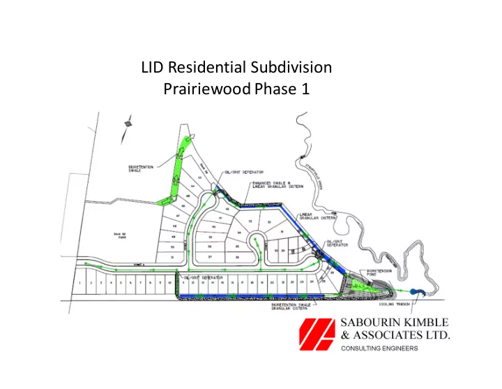
SLIDE 1
LID Residential Subdivision Prairiewood Phase 1
SLIDE 2 Site Location and Context
- South limit of Whitchurch Stouffville, west of
Tenth Line.
- Existing development to the north and west.
- Developable area bounded by
woodlot/wetland and Stouffville Creek valley corridor.
- Original MESP SWM proposal to discharge to
SWM pond north of site.
SLIDE 3
SLIDE 4
Draft Plan of Subdivision
SLIDE 5
Existing Grades
SLIDE 6 Stormwater Management Criteria
- Water Quality Control – satisfy the MOE
Enhanced Protection Guidelines.
- Erosion Control – detention of the runoff from
a 25 mm storm released over 97.2 hours.
- Water Quantity Control – Post development to
Pre‐development controls for the 2 year through 100 year storm as per the unit flow relationships from the overall Duffin Creek watershed model.
SLIDE 7 LID Concept
- Implementation of Low Impact Development
facilities distributed throughout the site including;
- 1. Extra topsoil depths on the lots,
- 2. Bioretention swales,
- 3. Enhanced swales,
- 4. Oil/grit Separators,
- 5. Granular cisterns,
- 6. Bioretention/dry quantity pond,
- 7. Outlet cooling trench.
SLIDE 8
LID Concept
SLIDE 9
Grading Plan
SLIDE 10 Water Quality and Erosion Controls
- Water Quality – Enhanced Protection Guidelines:
- 1. Oil Grit separators for the storm sewers (roads and
contributing lots),
- 2. 0.3 metre deep clear stone gallery below the
perforated pipe invert for contributing lots.
- Erosion Controls – runoff from 25mm storm
- 1. Provided in the clear stone gallery above the
perforated pipe invert.
SLIDE 11
Woodlot Bioretention Swale
SLIDE 12
Woodlot Bioretention Swale
SLIDE 13
SLIDE 14
Bioretention Swale & Granular Cistern South Limit of Subdivision
SLIDE 15
Bioretention Swale & Granular Cistern Profile
SLIDE 16
Bioretention Swale & Granular Cistern Section
SLIDE 17
SLIDE 18
Enhanced Swale & Linear Granular Cistern Northeast Limit of Subdivision
SLIDE 19
Enhanced Swale & Linear Granular Cistern Profile
SLIDE 20
Enhanced Swale & Linear Granular Cistern Section
SLIDE 21
SLIDE 22 Water Quantity Control
- Water Quantity control – 2 through 100 year
post development to pre‐development levels.
- 1. Provided in the dry bioretention pond above
a ponding depth of 0.25 metres.
- 2. 0.25 metre depth and below utilized to
provide polishing of low flows.
SLIDE 23
Bioretention Pond
SLIDE 24
Bioretention Pond Section
SLIDE 25
SLIDE 26
Proposed Overall Landscape Plan
SLIDE 27 Construction Implementation Strategy
- Fundamental approach – avoid construction
- f all granular galleries and landscape features
until after build‐out and green up.
- Provide separate Erosion Sedimentation
control plans for earthworks and underground servicing/house building.
SLIDE 28
Earthworks Sediment Control Plan
SLIDE 29
Underground Servicing Sediment Control Plan