LFEV - High Level Simplified Block Diagram Work Breakdown Structure - - PowerPoint PPT Presentation

lfev high level simplified block diagram work breakdown
SMART_READER_LITE
LIVE PREVIEW

LFEV - High Level Simplified Block Diagram Work Breakdown Structure - - PowerPoint PPT Presentation

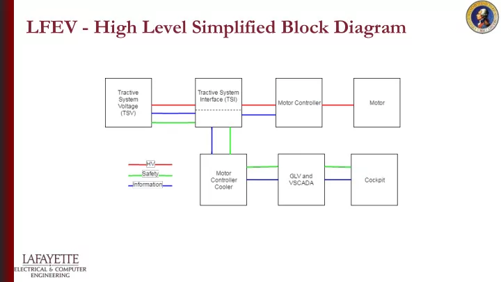
LFEV - High Level Simplified Block Diagram Work Breakdown Structure WBS Schedule PSL Interconnect / Cabling Complete Interconnection of all car subsystems Identifying and acquiring/purchasing all required parts for complete


slide-1
SLIDE 1

LFEV - High Level Simplified Block Diagram

slide-2
SLIDE 2

Work Breakdown Structure

  • WBS
  • Schedule
  • PSL
slide-3
SLIDE 3

Interconnect / Cabling

  • Complete Interconnection of all car subsystems
  • Identifying and acquiring/purchasing all required parts for complete integration
  • Assembling each cable based on schematic and subsystem specifications
  • Cable Testing
  • Cable Labeling
  • Cable Reworking based on System Diagram Updates
  • Acceptance Test Plan Wire Documentation
slide-4
SLIDE 4

Interconnect / Cabling

  • Wires - gauge based on voltage and current
  • Connectors

○ Deutsch DT Series ○ ITT Cannon PowerLock

DT Series PowerLock

slide-5
SLIDE 5

Tractive System Voltage [TSV]

slide-6
SLIDE 6

Tractive System Voltage [TSV]

  • Produced 3 Additional TSV Accumulator Packs

○ Maintained the existing TSV Accumulator Pack ○ Recommended slight modifications to PacMAN

  • Tested integration of accumulator, dynamometer, GLV, and basic SCADA (up to

160A)

  • Comprehensive Documentation of TSV Subsystem
slide-7
SLIDE 7

Systems Engineering

Flow of information throughout the car on the CAN bus Revamped Pacman control panel and display

slide-8
SLIDE 8

Tractive System Interface [TSI]

  • PCB Schematic Design
  • PCB Layout
  • Box Integration and Wiring
slide-9
SLIDE 9

Tractive System Interface [TSI]

  • PCB Schematic Design

○ Throttle Plausibility

  • PCB Layout
  • PCB Build and Debug
  • Firmware
slide-10
SLIDE 10

Tractive System Interface [TSI]

  • Inventor Box Layout
  • IMD Integration
  • HV Bars
slide-11
SLIDE 11

Dynamometer

  • Ran tests required for other teams
  • Fixed communication to the power supply to be able to control power supply and
  • btain current Amperage and Voltage
  • Expanded upon the existing code base to add new functionality and added new

calculation parameters

  • Assisted other teams in integrating their subsystems into the Dyno system.
slide-12
SLIDE 12

Controller Cooling

Software Design of Cooling Controller

  • Sensors integration
  • Mode selection
  • Auto - change temp threshold in run-time
  • Manual - change speed % in run-time
  • LCD interface
  • CAN communication
  • 24V Safety-Loop relay control
slide-13
SLIDE 13

Controller Cooling

  • Design and Build the box of cooling controller

○ Mounting of arduino board, circuit board, connector panels, etc.

  • Preliminary documentation

○ Drawing of Mounting

Block diagram ○ Electrical schematic diagram

slide-14
SLIDE 14
  • GLV Power
  • Safety Loop
  • Vehicle Computer Interface
  • Vehicle User Interface

Grounded Low Voltage [GLV]

slide-15
SLIDE 15

Grounded Low Voltage [GLV]

  • Battery research and acquisition
  • GLV_BOB schematic, layout, parts acquisition and testing
  • Car Integration
slide-16
SLIDE 16

Grounded Low Voltage [GLV]

  • Mechanical components of the GLV system

○ Enclosure Layout ○ Enclosure panels ○ Dyno room panels

  • Dyno room integration
slide-17
SLIDE 17

Vehicle Supervisory Control and Data Acquisition [VSCADA]

  • Backend database

○ Can dump -> database

  • User Interface

○ Graphics

slide-18
SLIDE 18

Vehicle Supervisory Control and Data Acquisition [VSCADA]

  • Webserver

○ Handles GET requests ○ Can query based on parameters

  • User Interface

○ More graphics

slide-19
SLIDE 19

John Gehrig Board [JGB]

  • UART

○ Fixed and modified original library ○ Implemented two way communication

  • CAN Bus

○ Implemented receiving ○ Keyboard to CAN / CAN Dump using UART

slide-20
SLIDE 20

Cell App

  • Android Application (Version 4.0.3+)

○ Connection to VSCADA through web server ○ Display of data with various views ■ Automatically updating data and views ○ Fully customizable interface

slide-21
SLIDE 21

Physics Modeling & Cruise Control

  • Research of physical relation of integration of Formula Electric car
  • Research of theoretical physical behaviour of MCM system
  • Experimental determination of:

○ Mathematical relation of MCM I/O ○ Electric motor plausibility for Formula Electric car ○ Dynamic and Static Model lookup table ○ MCM system efficiency ○ Accurate foundation for cruise control

slide-22
SLIDE 22

Budget

slide-23
SLIDE 23

Communications

  • Worked to raise awareness of the work being done on campus
  • Documented throughout the semester the work being done and produced overall

video summary documenting the “essence” of the project

  • Research Proposal for what the next big ECE 492 project should be
  • User Manual Videos