
SLIDE 1
Reinforced Concrete II Hashemite University
- Dr. Hazim Dwairi
1
The Hashem ite University Departm ent of Civil Engineering
Lecture 2 Lecture 2 – – One One-
- way Joist
way Joist Slab System Slab System
Dr Hazim Dwairi Dr Hazim Dwairi
Reinforced Concrete II Reinforced Concrete II
- Dr. Hazim Dwairi
- Dr. Hazim Dwairi
The Hashemite University The Hashemite University
- Dr. Hazim Dwairi
- Dr. Hazim Dwairi
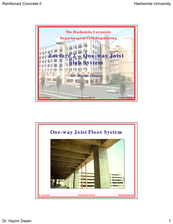
One One-
- way Joist Floor System
way Joist Floor System
Reinforced Concrete II Reinforced Concrete II
- Dr. Hazim Dwairi
- Dr. Hazim Dwairi
The Hashemite University The Hashemite University