Lab 1 Preparation Sample C Programs C review (Chapter 5, - - PDF document

lab 1 preparation sample c programs
SMART_READER_LITE
LIVE PREVIEW

Lab 1 Preparation Sample C Programs C review (Chapter 5, - - PDF document

CEG411/611 Microprocessor EVB (Evaluation Board): Axiom CSM12C32 Based System Design (www.axman.com) What is this course about? Computer : Processor, Memory, I/O Chip: MC9S12C32 from Freescale (formerly, a Processor Memory


slide-1
SLIDE 1

1

CEG411/611 Microprocessor Based System Design

  • What is this course about?
  • Computer : Processor, Memory, I/O
  • Microprocessor versus microcontroller
  • Embedded Systems

Processor I/O Memory Bus

  • EVB (Evaluation Board):

Axiom CSM12C32 (www.axman.com)

  • Chip: MC9S12C32 from

Freescale (formerly, a Motorola division)

– For chip documentation in PDF files, see C:\68HC12\ 9S12C32_Chip

  • 68HC12 versus 68HCS12

Lab 1 Preparation

  • Monitor, MON12, Monitor commands (Sec.

3.5.3) MD, MM, LOAD, CALL

  • Address versus data
  • Hexadecimal number system and Memory map
  • C, Assembly, Machine Code
  • ICC12 and as12
  • Step by step instructions
  • S record file, list file, map file

Sample C Programs

  • C review (Chapter 5, sample_c.c)

– main( ), function call – data types (char, unsigned char, int, short, long, float) – Condition check (true, false, if, else) – for loop, while loop – putchar(), puts(), printf()

  • tone.c : timer, output compare (Sec 8.6)
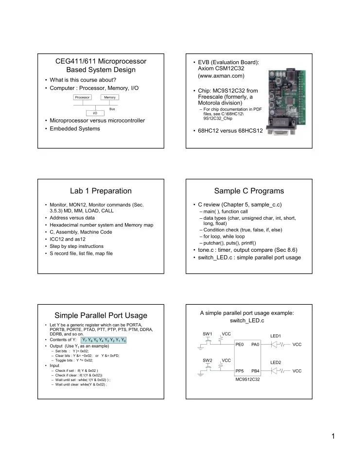
  • switch_LED.c : simple parallel port usage
  • Let Y be a generic register which can be PORTA,

PORTB, PORTE, PTAD, PTT, PTP, PTS, PTM, DDRA, DDRB, and so on.

  • Contents of Y: Y7 Y6 Y5 Y4 Y3 Y2 Y1 Y0
  • Output (Use Y1 as an example)

– Set bits : Y |= 0x02; – Clear bits : Y &= ~0x02; or Y &= 0xFD; – Toggle bits : Y ^= 0x02;

  • Input

– Check if set : if( Y & 0x02 ) – Check if clear : if( !(Y & 0x02)) – Wait until set : while( !(Y & 0x02) ) ; – Wait until clear: while(Y & 0x02) ;

Simple Parallel Port Usage

A simple parallel port usage example: switch_LED.c

MC9S12C32 PB4 PE0 PP5 PA0 SW1 VCC SW2 VCC VCC LED1 VCC LED2

slide-2
SLIDE 2

2

Measuring Pulse Width Without Using Input Capture

  • Use while loops and read TCNT to get T1,

T2

  • If(T2 > T1) T = T2 – T1;

else T = 0xffff – T1 + T2 + 1;

  • Timer Overflow?

6812

Interrupt Programming

  • Interrupt versus polling
  • Interrupt programming

– Write an ISR (interrupt service routine) – Register the ISR, p. 268 – Enable ISR (locally and globally)

  • tone_interrupt.c example
  • On EVB, pressing the reset button clears

the MON12 (user) interrupt vector table contents

  • Chapter 6

ADC (Chapter 12)

  • ADC basics, a 2Lbit ADC example, Sec.

12.2.4, Example 12.1

Analog = VL + Digital * (VHLVL)/(2NL1)

  • ADC Internal: Successive Approximate

Method, Sec. 12.2.3

  • Signal Conditioning Circuits based on OP

Amp: Sec. 12.2.5 & 12.2.6

  • 6812 ADC Programming: Sec. 12.3

– adc_scan.c

ADC Timing (ATDCTL4), p. 602

  • ATD Clock = Bus Clock / [2(PRS+1)]

– Bus Clock : 24 MHz on EVB – PRS : bits 4 to 0 of ATDCTL4

  • ATD Conversion Time per Sample =

[2 + 2(SMP+1) + B] ATD clock cycles

– SMP : bits 6 and 5 of ATDCTL4 – B: 8 or 10 (for 8Lbit and 10Lbit ADC, respectively)

Assembly Programming

  • Why assembly programming?

– Understand computer/C internal operations – More efficient coding

  • CPU Registers (Sec. 1.8)

D (A:B) : accumulator; X, Y: index registers; SP : Stack Pointer; PC: Program Counter CCR : Condition Code Register S X H I N Z V C

  • Memory Addressing

– BigLEndian versus LittleLEndian – Memory Mapped I/O

  • A sample assembly program (tonevb.asm)

– Label, Opcode, Operands, Comments – Assembler directives (e.g., ORG)

CPU Memory 16Lbit Address 8/16Lbit Data

slide-3
SLIDE 3

3

  • Load/Store Instructions (Sec. 1.11.1) and

Addressing Modes (Sec. 1.9)

  • Examples

– LDAA #$55 immediate mode – LDAA #55 immediate mode – LDD #$0F20 immediate mode – LDAA $55 direct mode – LDAA $0F20 extended mode – LDD $0F20 extended mode – LDAB 3,X indexed mode

  • LDX, LDY, LEAS, LEAX, LEAY

– LEAS L4,SP : SP ← (SP)L4

(to allocate space for local variables for subroutines)

  • STAA, STAB, STD, STS, STX, STY

Example: int m, n; // assume m is at $3000 // assume n is at $3002 m = n + 5; LDD $3002 ADDD #5 STD $3000 How about char instead of int?

  • More instructions (Sec. 1.11)

– Transfer (register to register) and Exchange (swap registers): TAB, TAP, TBA, ....; EXG, XGDX, XGDY – Move (memory to memory): MOVB, MOVW – Add and Subtract (always involves CPU registers)

  • Register + Register : ABA, ABX, ABY
  • Register + Memory : ADCA, ADCB, ADDA, ADDB,

ADDD

  • Register – Register : SBA
  • Register – Memory : SBCA, SBCB, SUBA, SUBB,

SUBD

  • Assembler Directives (Sec. 2.3)

– ORG (Origin), EQU (Equate) – Specify Constants: fcb (Form Constant Byte, or db), fcw (Form Constant Word, or dw), fcc (Form Constant Character, String), fill – Reserve Space: rmb (reserve memory byte), rmw (reserve memory word)

  • Examples

ORG $3800 array fcb $11,$22,$33,’5,25,100 buf rmb 20 msg fcc “Hello World” tmp fill $11,20

  • Program Loops (Sec. 2.6)

– Loop constructs – Branch conditions/instructions compare (A to B, a register to a memory)

  • r

test (A, B, or a memory location) S X H I N Z V C CCR branch (BRA, BEQ, BNE, BLS, ...)

  • Examples 2.14 (p. 68), 2.15

– Draw flowchart – Revise flowchart

  • Example 2.17

– BRCLR oprand,mask,label branch to label if the bit(s) is (are) clear while(!(TFLG1 & 0x01)); // wait until flag is set // the above C statement is equivalent to here BRCLR $004E,$01,here Note that $004E is the address of TFLAG1 – BRSET oprand,mask,label

slide-4
SLIDE 4

4

Subroutine Calls (Chapter 4)

  • Stack, Stack Pointer, Push, Pull

– PSHA, PSHB, PSHD, PSHX, PSHY : Decrement (SP) first, then write data – PULA, PULB, PULD, PULX, PULY : Read data first, then increase (SP)

  • Example:
  • Ex. 4.1

LDS #$3E00 LDAA #$3B LDD #$302F PSHA PSHD

  • BSR, JSR, RTS, Caller, Callee (Sec. 4.4)

BSR SORT ........ SORT ........ ........ RTS

  • Parameter Passing, Result Returning, and

Allocation of Local Variables (Sec. 4.5)

– Using registers versus using stack

  • Stack Frames (Sec. 4.6), Ex. 4.3
  • Example C versus Assembly

Local Variables Saved Registers Return Address Incoming Parameters & Return Values

  • 1. Caller:

PSHX

  • 2. Caller:

BSR

  • 3. Callee:

PSHD

  • 4. Callee:

LEAS L4,SP void main() { int a, b; a = sum(b, 3); } int sum(int x, int y) { int s; s = x + y; return s; } LDD 5,sp *** b PSHD LDD #3 PSHD LEAS L2,sp *** result JSR Sum .... Sum: PSH... *** save reg LEAS L2,sp *** s ......

More Timer Functions

  • Timer Overflow (p. 367): TSCR2 bit 7 (TOI),

TFLAG2 bit 7(TOF)

  • Input Capture (Sec. 8.5) and Examples
  • RealLTime Interrupt (Sec. 6.7):

CRGINT bit 7 (RTIE), CRGFLG bit 7 (RTIF) n = RTICTL bits 6L4; m = RTICTL bits 3L0 OSCCLK (16MHz on EVB)/[(m+1)2(n+9)]

  • Pulse Accumulator (Sec. 8.7): a 16Lbit counter
  • Pulse Width Modulation (PWM) (Sec. 8.10)
  • Parallel Ports, I/O Synchronization and

Handshaking (Sec. 7.4)

– Strobe vs. Handshake – Input/Output Handshaking Protocols

  • Serial Interface (Chap. 9 & 10):

– SCI vs. SPI – SCI: RSL232, StartLbit, StopLbit, Parity – SPI (p.482): SCK, SS, MISO, MOSI – Other Serial Interface Protocols: USB, PCI Express, SATA, Ethernet