
SLIDE 1
KEKB / SuperKEKB
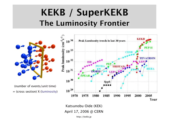
The Luminosity Frontier
Katsunobu Oide (KEK) April 17, 2006 @ CERN
http://kekb.jp
(number of events/unit time) = (cross section) X (luminosity)
KEKB / SuperKEKB The Luminosity Frontier (number of events/unit - - PowerPoint PPT Presentation
KEKB / SuperKEKB The Luminosity Frontier (number of events/unit time) = (cross section) X (luminosity) Katsunobu Oide (KEK) April 17, 2006 @ CERN http://kekb.jp KEKB = Asymmetric Double-Ring Collider for B-Physics 8 GeV Electron + 3.5 GeV
Katsunobu Oide (KEK) April 17, 2006 @ CERN
http://kekb.jp
(number of events/unit time) = (cross section) X (luminosity)
1989: Design work started. 1994: Approval of the budget, construction started. June 1995: KEKB Design Report
Commissioning of the injector Linac started.
First beam at LER. May 1999: Belle roll-in. June 1999: First event at Belle.
World record of the luminosity, 3.4 /nb/s.
World record of the integrated luminosity, 100 /fb. May 2003: Exceeded the design luminosity, 10 /nb/s.
Exceeded 12 /nb/s & 200 /fb.
13.9 /nb/s & 300 /fb. May 2005: 15.3 /nb/s & 420 /fb.
… continues rewriting own records …
KEKB = Asymmetric Double-Ring Collider for B-Physics
8 GeV Electron + 3.5 GeV Positron
Superconducting cavities (HER) e- e+ ARES copper cavities (LER) 8 GeV e- 3.5 GeV e+ Linac e+ target ARES copper cavities (HER) Belle detector
KEKB B-Factory
TRISTAN tunnel
Nikko KEKB Rings Belle Linac KEK Site
1034 cm-2s-1 600 /pb/day
Achieved >500 /fb in 6.5 years. (Initial Goal: 100 /fb in 3 years.)
1034
We are here
54 /fb/mo 27 /fb/mo.
Next Milestone
Crab Cavity Beam Test
SuperKEKB
KEKB design 10 30 10 31 10 32 10 33 10 34 10 35 10 36 1 10 10
2
10
3
10 30 10 31 10 32 10 33 10 34 10 35 10 36 1 10 10
2
10
3
DAFNE ADONE BEPC CESR PEP-II KEKB LEP LEP-II TRISTAN PETRA DORIS SPEAR VEPP-2M VEPP-4M PEP ILC
CMS Energy (GeV) Luminosity (cm-2s-1)
Shutdown for upgrade
Data doubling time Integrated Luminosity
leader in the luminosity frontier.
at KEKB, together with a few modifications.
Crab cavities will be installed and tested with beam in 2006. The superconducting cavities will be upgraded to absorb more higher-order mode power up to 50 kW. The beam pipes and all vacuum components will be replaced with higher-current-proof design. The state-of-art ARES copper cavities will be upgraded with higher energy storage ratio to support higher current.
SuperKEKB
e+ 4.1 A e- 9.4 A β*y = σz = 3 mm
will reach 8 × 1035 cm-2s-1.
L = γ± 2er
e
1+ σ y
*
σ x
*
I±ξ±y βy
*
RL Ry
Three factors to determine luminosity:
e
*
*
*
Stored current: 1.36/1.75 A (KEKB) → 4.1/9.4 A (SuperKEKB) Beam-beam parameter: 0.059 (KEKB) → >0.24 (SuperKEKB) Vertical β at the IP: 6.5/5.9 mm (KEKB) → 3.0/3.0 mm (SuperKEKB)
Lorentz factor Classical electron radius Beam size ratio Geometrical reduction factors due to crossing angle and hour-glass efgect
Luminosity: 0.16 ×1035 cm-2s-1 (KEKB) 8×1035 cm-2s-1 (SuperKEKB)
New Parameter Set for 8×1035 -- by K. Ohmi
10
beta, bunch length as 4 ×1035 cm-2s-1.
slices to reduce the numerical noises and the instability, using a new supercomputer at KEK.
ratio or smaller horizontal emittance.
but may help the lifetime.
11
εx=18nm, εy=0.09nm, βx=0.2m βy=3mm σz=3mm Lower coupling gives higher luminosity, but numerical instability occurs with less number of slices.
5 slices 10 slices
2e+35 4e+35 6e+35 8e+35 1e+36 0.02 0.04 0.06 0.08 0.1 L ey (nm) 10 slice ex=9nm
ex = 18 nm ex = 9 nm
particles with z.
εx=24 nm εy=0.18nm βx=0.2m βy=1mm σz=3mm
coating, bellows, collimators, etc.
crossing angle 30 mrad
Head-on(crab)
(Strong-strong simulation)
Crab crossing will boost the beam-beam parameter up to 0.19! Superconducting crab cavities are under development, and will be installed in KEKB in 2006.
I.R. 20 I.R. 90 I.D. 188 I.D. 120 I.D. 30 I.D. 240 Input Coupler Monitor Port I.R.241.5 483 866 Coaxial Coupler scale (cm) 50 100 150(at the optimum tune)
Cryostat & couplers
2006/3/21 2006 KEKB Review 20
Beam duct with two antechambers (2005)
Model: for wiggler section
OFC(t6), w224, h94, L4.7 m
Fabrication methods:
Forming (from plates)
Manufacturing was successful.
Degree of accuracy should be
improved in future
Forming Inside view Final check
2006/3/21 2006 KEKB Review 21
Application of Ver.2 to antechamber-type bellows
Manufactured at BINP (2005) Copper cooling channel
Improve cooling of teeth
Two bellows chamber were
installed into LER wiggler (2005).
No problem was found up to 1.7 A.
2006/3/21 2006 KEKB Review 22
Application to bellows chamber and ducts (2005)
MO-flange was applied to beam duct with ante-chambers
and their bellows chambers, and installed into LER.
No problem was found up to 1.7 A.
Temperature of bellows was almost same to conventional ones
(circular). ~30 °C .
MO-type flange for bellows chamber MO-type flange for beam duct with antechambers for wiggler section SS flange Cu gasket Bellows chamber
2006/3/21 2006 KEKB Review 23
Features
Ceramics support
Little interference with beam
Carbon head
Little damage by beam
With HOM absorber (SiC)
Stealth type
Has been studied since 2003
R&D points (still preliminary)
Trapped mode Heating of head Charge up Experimental demonstration Ver.4 at present Beam duct Support (ceramics) Head (C) SiC Beam SiC
Positron Beam Chamber Sample Manipulator Electron Source Gate Valve Sample Manipulator Electron Monitor
LCとの連携(2)(加藤) In-situ Measurement System of Secondary Electron Yields at Positron Ring of the KEKB
★ In-situ Measurements of Secondary Electron Yields at Surfaces Exposed to Positron Beam of the KEKB ★ Primary Electron Beam : 50eV~5KeV, Beam Scan Capability ★ Quick Sample Exchanging Capability with Loadlock Chamber (N.A. @CERN) ★ Electron Activity Monitoring Close to Sample @ Beam Chamber
◆ PY2005 :
1.
designing and manufacturing of the system
2.
installation of a copper beam chamber in a straight section at the KEKB.
3.
a measurement system is being tested in a lab..
4.
the whole setup will be installed onto the chamber and the measurement will get started. ◆ PY2006 :
1.
a series of the experiments
2.
installation of a setup for short & long term exposure capability
3.
installation of a setup for gas puffing capability ( H2, CO etc )
4.
installation of a residual gas analyzer
<Features> <Achievement and Plan>
Loadlock Chamber
Construction of QCS R&D Magnet
(2-4) 12 Cured Coils and curing 6 layer coils all at once
(1) 12 cured double pan-cake coils. (2) Curing process of 6 layer coils. This process is necessary for improving the field quality in the
(1) (2)
Superconducting Cavity
Storing world’s highest beam current of 1.2A. Input coupler has been operated up to 380kW. Ferrite Higher Order Mode (HOM) absorber working at 10 kW (has achieved 12kW at 1.2 A). SuperKEKB challenges: The expected power load to the HOM absorber is 50 kW/cavity at 4.1 A, (even) with a larger beam pipe of 220 mmφ. HOM damper upgrade may be needed.
we observed a strong longitudinal instability at the ATF.
longitudinal CBI with the BxB feedback system using Gproto down to 1/10.
strongest coupled-bunch mode. (218+n*357 MHz)
necessary to build and install a good feedback kicker. A prototype of the new bunch-by-bunch feedback system (G-board / Gproto) was tested at KEKB and
with 4 structures.
Prototype C-band structure installed and tested at linac using actual beam (2003). Measured field gradient of 41 MV at 43 MW agrees with expectation.
aperture of C-Band section and to meet IR dynamic aperture restrictions.
– Electron DR may be considered later to reduce injection backgrounds in physics detector, but for now only positron DR considered.
before C-Band accelerating section.
e+ Damping Ring e+ production J-ARC B T e- gun
Oku-yen = 0.9 M$ Detector upgrade is not included.
(International support may be necessary to make this project real.)
made with 8 ×1035 cm-2s-1 luminosity.
magnets, rf cavities and power sources are reused.
33