IST Today! Hw#5: Circuit design in Logisim A - - PowerPoint PPT Presentation

ist today
SMART_READER_LITE
LIVE PREVIEW

IST Today! Hw#5: Circuit design in Logisim A - - PowerPoint PPT Presentation

OK Recursing? Jotto Corner Faye / Garrett OKer than before? cs5 guess my guess alien: 1 diner: 2 diner: 0 savvy: 1 party: 0 savvy: 1 judge: 2 ghost: 0 ghost: 2 plumb: ? ????? : ? plumb: ? Submission Site vs. Sakai? Sakai can


slide-1
SLIDE 1

IST Today!

Minterm Expansion Principle

That's minterm, NOT midterm

Hw#5: Circuit design in Logisim

OK Recursing? OKer than before?

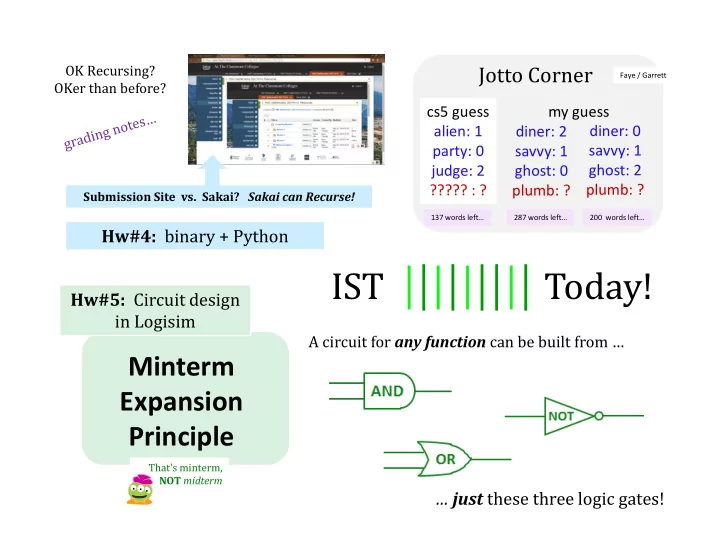
A circuit for any function can be built from …

… just these three logic gates!

Submission Site vs. Sakai? Sakai can Recurse!

Jotto Corner

cs5 guess alien: 1 party: 0 judge: 2 ????? : ? my guess diner: 2 savvy: 1 ghost: 0 plumb: ?

Faye / Garrett

diner: 0 savvy: 1 ghost: 2 plumb: ?

200 words left… 287 words left… 137 words left…

Hw#4: binary + Python

slide-2
SLIDE 2

def decipher( S ): """ TESIJHYDW - je tusyfxuh jxyi tesijhydw, zkij hkd tusyfxuh ed yj. """ … code here …

Creativity with Caesar...

slide-3
SLIDE 3

def decipher( S ): """ DOCSTRING - to decipher this docstring, just run decipher on it. """ … code here …

Creativity with Caesar...

my favorite not-fully-working decipher…

slide-4
SLIDE 4

def decipher( S ): """ This works sometimes """ return encipher( S, 3 )

Creativity with Caesar...

and this docstring is 100% correct!

solved with whatever resources were available

slide-5
SLIDE 5

def decipher( S ): """ This works sometimes """ return encipher( S, 3 )

Creativity with Caesar...

and this docstring is 100% correct!

solved with whatever resources were available MacGyver, ~1987

slide-6
SLIDE 6

MacGyver, back for 2016…

Thirty years ago, Angus MacGyver was the most iconic engineer hero on TV. In 2015, we’re looking for new engineering heroes. The USC Viterbi School of Engineering and the National Academy of Engineering are partnering with Lee Zlotoff, creator of the MacGyver series to identify and develop the first great TV show featuring women engineers. Five winners receive $5,000 each and be given the rare opportunity to be paired with top Hollywood mentors [to develop the show]. Please submit your ideas to www.thenextmacgyver.com We’re looking for ideas only at this stage. No completed scripts necessary. All genres welcome. We’re not looking to re-make MacGyver. We’re looking for that next show in the spirit of MacGyver, with a female protagonist who uses engineering to solve problems. Who can submit: Anyone worldwide over 18. Screenwriters, engineers, students, non-students and essentially anyone who has a good idea and cares deeply about exciting young people to STEM fields. Submission deadline: April 17

slide-7
SLIDE 7

def decipher( S ): """ This works sometimes """ return encipher( S, 3 )

Designing physical devices that work all the time!

This week

slide-8
SLIDE 8

42

101010

In a computer, each bit is represented as a voltage (1 is +5v and 0 is 0v)

9

001001

ADDER circuit

110011

51

Computation is simply the deliberate combination of those voltages!

What's in that green box?

(3) read output voltages (1) set input voltages (2) perform computation

Richard Feynman: "Computation is just a physics experiment that always works!"

slide-9
SLIDE 9

Part 1: Represent your f'n as bits…

Any function can be represented using only bits… x y

1 1

circuit output

1 1

IN OUT

c

1 1 1 1 1 1 1 1 1 1 1 1

slide-10
SLIDE 10

All computations… …are simply f'ns of bits

00 00 00 01 00 10 00 11 01 00 01 01 01 10 01 11 10 00 10 01 10 10 10 11 11 00 11 01 11 10 11 11 000 001 010 011 001 010 011 100 010 011 101 100 100 011 101 110 A B

binary inputs A and B

  • utput, A+B

bitwise addition function sum

slide-11
SLIDE 11

Part 2: Arrange logic gates to match…

x y 1 1 1 1 AND(x,y) 1 AND outputs 1 only if ALL inputs are 1 x y 1 1 1 1 OR(x,y) 1 1 1 OR outputs 1 if ANY input is 1 NOT reverses its input

input

  • utput

x 1 NOT(x) 1

input

  • utput

input

  • utput

AND OR NOT

not just theoretical models!

slide-12
SLIDE 12

Our building blocks: logic gates

AND outputs 1 only if ALL inputs are 1 OR outputs 1 if ANY input is 1 NOT reverses its input

AND OR NOT

These circuits are physical functions of bits… … and all mathematical functions can be built from them!

slide-13
SLIDE 13

AND

AND outputs 1 when ALL inputs are 1

  • therwise it outputs 0

inputs

  • utput

AND

drill sergeant metaphor? Strict! Everything input must be True to output a True

slide-14
SLIDE 14

AND

AND's function:

inputs

  • utput

AND x y 1 1 1 1 AND(x,y) 1

input

  • utput

x y

  • utput

Strict! Everything input must be True to output a True

slide-15
SLIDE 15

AND

AND outputs 1 when ALL inputs are 1

  • therwise it outputs 0

inputs

  • utput

AND

How many different input combinations yield an

  • utput of 0 here?

Strict! Everything input must be True to output a True

slide-16
SLIDE 16

AND

inputs

  • utput

AND x y 1 1 1 1 AND(xyzw) 1 z 1 1 w 1 1 w

  • utput

input

  • utput

…12 more rows not shown…

z y x

fifteen 0s

  • ne 1

AND's function:

Strict! Everything input must be True to output a True

slide-17
SLIDE 17

OR

OR outputs 1 when ANY input is 1

It outputs 0 only if all inputs are 0. inputs

  • utput

OR

camp counselor metaphor? easy-going: if anything is OK, everything's OK

slide-18
SLIDE 18

OR

inputs

  • utput

x y 1 1 1 1 OR(x,y) 1 1 1

input

  • utput

x y

  • utput

OR's function:

OR

easy-going: if anything is True, the output is True

slide-19
SLIDE 19

OR

OR outputs 1 when ANY input is 1

It outputs 0 only if all inputs are 0. inputs

  • utput

How many different 4-input combinations yield an

  • utput of 1?

OR

easy-going: if anything is OK, everything's OK

slide-20
SLIDE 20

OR

inputs

  • utput

OR w

  • utput

z y x x y 1 1 1 1 OR(xyzw) 1 1 1 z 1 1 w 1 1

input

  • utput

…12 more rows not shown…

1 fifteen 1s

  • ne 0

OR's function:

easy-going: if anything is OK, everything's OK

slide-21
SLIDE 21

NOT

inputs

  • utput

NOT

"NOT bubble"

(optional – or the only thing needed!)

x x 1 NOT(x) 1

input

  • utput
  • ne 1
  • ne 0

NOT's function:

slide-22
SLIDE 22

Our building blocks: logic gates

x y 1 1 1 1 AND(x,y) 1 AND outputs 1 only if ALL inputs are 1 x y 1 1 1 1 OR(x,y) 1 1 1 OR outputs 1 if ANY input is 1 NOT reverses its input

input

  • utput

x 1 NOT(x) 1

input

  • utput

input

  • utput

AND OR NOT

slide-23
SLIDE 23

Claim !?

  • We need only these three building

blocks to compute anything at all

AND OR

NOT

AND outputs 1 iff ALL its inputs are 1 OR outputs 1 iff ANY input is 1 NOT reverses its input

slide-24
SLIDE 24

What inputs make this circuit output 1?

Logisim

What inputs make this circuit output 0?

A circuit…

slide-25
SLIDE 25

What are ALL of its outputs?

Logisim A circuit…

c

slide-26
SLIDE 26

Rails

What are the differences between these two circuits? Any advantages

  • f this "rails"

approach?

using rails for not x, not y, + not c

disadvantages?

slide-27
SLIDE 27

Fill in the function values for this circuit (the truth table)

(3) For each possible input, write the circuit output in the truth table above.

A B C D

(4) Could this circuit use fewer logic gates? If so, how?!

If not, how do you know?!

Quiz

Name(s) ___________________________________

Each input x, y, and z can independently be 0 or 1, for eight possible inputs:

y z

1 1 1 1

inputs

1 1 1 1

x

1 1 1 1

  • utput

Each output is 0 or 1

(1) This circuit uses 8 logic gates – how many of each? AND ___ OR ___ NOT ___ 1 (2) Follow the inputs of x=1, y=1, z=1 and see why the overall output is 1 ... (already labeled)

circuit

slide-28
SLIDE 28

Fill in the function values for this circuit (the truth table)

A B C D

Quiz

y z

1 1 1 1

inputs

1 1 1 1

x

1 1 1 1

  • utput

Each output is 0 or 1

1

circuit

Try this on the back page first…

(3) For each possible input, write the circuit output in the truth table above. (4) Could this circuit use fewer logic gates? If so, how?!

If not, how do you know?!

Each input x, y, and z can independently be 0 or 1, for eight possible inputs:

(1) This circuit uses 8 logic gates – how many of each? AND ___ OR ___ NOT ___ (2) Follow the inputs of x=1, y=1, z=1 and see why the overall output is 1 ... (already labeled)

slide-29
SLIDE 29

Real! logic gates...

Hex NOT gate

slide-30
SLIDE 30

Real? logic gates

1:31 :41 "It's not real unless it can be done in Minecraft."

  • perhaps not a

real quote

https://www.youtube.com/watch?v=P7E4K5D834g "Minecraft Logi Gates" https://www.youtube.com/watch?v=r7N3K8ulEEM "Minecraft Logic Gates Water"

slide-31
SLIDE 31

The claim…

  • We need only these three building blocks

to compute anything at all AND OR

NOT

AND outputs 1 only if ALL its inputs are 1 OR outputs 1 if ANY input is 1 NOT reverses its input

slide-32
SLIDE 32

The proof… !

  • We need only these three building blocks

to compute anything at all AND OR

NOT

AND outputs 1 only if ALL its inputs are 1 OR outputs 1 if ANY input is 1 NOT reverses its input

slide-33
SLIDE 33

Specify a truth table defining any function you want

A constructive proof… !

x y 1 1 1 1 f(x,y) 1 1

input

  • utput

i ii

For each input row whose

  • utput needs to be 1, build

an AND circuit that outputs 1

  • nly for that specific input!

iii

OR them all together

Hey! This is a 3-i'ed proof!

slide-34
SLIDE 34

Specify a truth table defining any function you want

A constructive proof…

x y 1 1 1 1 f(x,y) 1 1

input

  • utput

i ii

For each input row whose

  • utput needs to be 1, build

an AND circuit that outputs 1

  • nly for that specific input!

iii

OR them all together OR The ZERO rows ALREADY work – with no connections at all !

x y x y We ensure this OR

  • utputs zero by

default.

slide-35
SLIDE 35

Specify a truth table defining any function you want

A constructive proof…

x y 1 1 1 1 f(x,y) 1 1

input

  • utput

i ii

For each input row whose

  • utput needs to be 1, build

an AND circuit that outputs 1

  • nly for that specific input!

iii

OR them all together OR

x y x y

NOT AND

Does this wire turn on for the red input row? Does this wire turn on for any other input rows?

slide-36
SLIDE 36

Specify a truth table defining any function you want

A constructive proof…

x y 1 1 1 1 f(x,y) 1 1

input

  • utput

i ii

For each input row whose

  • utput needs to be 1, build

an AND circuit that outputs 1

  • nly for that specific input!

iii

OR them all together OR

x y x y

NOT AND NOT AND

blue row?

  • ther rows?
slide-37
SLIDE 37

Specify a truth table defining any function you want

A constructive proof…

x y 1 1 1 1 f(x,y) 1 1

input

  • utput

i ii

For each input row whose

  • utput needs to be 1, build

an AND circuit that outputs 1

  • nly for that specific input!

iii

OR them all together OR

x y x y

NOT AND NOT AND

blue row?

  • ther rows?
slide-38
SLIDE 38

Specify a truth table defining any function you want

A constructive proof…

x y 1 1 1 1 f(x,y) 1 1

input

  • utput

i ii

For each input row whose

  • utput needs to be 1, build

an AND circuit that outputs 1

  • nly for that specific input!

iii

OR them all together OR

x y x y

NOT AND NOT AND

blue row?

  • ther rows?
slide-39
SLIDE 39

Minterm?

A minterm is an AND gate connected to all input bits - either directly or inverted

slide-40
SLIDE 40

Each minterm selects one input:

What 3-bit input makes this AND gate output a 1?

a minterm is an AND gate that "selects" a single input

slide-41
SLIDE 41

(2) Draw the upstream wires that will implement this function as a circuit. Hint: Determine the input that turns each AND gate – each minterm -- to True

A B C D

(Extra #1) Could you replace the OR gate with ANDs and NOTs – so ORs aren't needed at all?! (1) Fill in the function values (the truth table) for this circuit…

y c

1 1 1 1

input

1 1 1 1

x

1 1 1 1

  • utput

A B C D

y c

1 1 1 1

input

1 1 1 1

x

1 1 1 1

  • utput

1 1 1 1

Take 2…

(Extra #2) How could these two circuits can implement any binary addition at all !?

c

slide-42
SLIDE 42

OR else ?!

Can you get rid of ORs by using

  • nly NOTs and ANDs?

OR

x y 1 1 1 1

OR(x,y)

1 1 1

input

  • utput

x y

x OR y

slide-43
SLIDE 43

A full adder sums three input bits to create a 2-bit binary output

3 individual bits of input 2 bits of output: a binary #

cout sum

0 0 0

cin

0 0 1 0 1 0 0 1 1 1 0 0 1 0 1 1 1 0 1 1 1 0 0 0 1 0 1 1 0

x y

0 1 1 0 1 0 1 1

Lab5: adders!

these columns look familiar!

the full adder

FA

x y cin sum cout

slide-44
SLIDE 44

A full adder sums three input bits to create a 2-bit binary output

3 individual bits of input

Lab5: adders!

the full adder

FA

x y cin sum cout

connect these directly…

2 bits of output: a two-bit binary #

Use this in lab this week!

sum carryout

slide-45
SLIDE 45

0 1 1 1 1 1 0 1

Compose!

+

Any binary addition at all?

8 bits in 5 bits out

Do you see how to use

  • ur Full Adders here?
slide-46
SLIDE 46

0 1 1 1 1 1 0 1

Compose!

+

4-bit Ripple-Carry Adder

8 bits in 5 bits out

We've used four full adders here… .

slide-47
SLIDE 47

It looks pretty wiry to me!

A zombie-themed ripple-carry adder

an "official" adder…

slide-48
SLIDE 48

relative scale…

slide-49
SLIDE 49

Many adders!

These aren't Easter Eggs, they're adder eggs!

slide-50
SLIDE 50

Ridin' the Rails !

chugging right along…

slide-51
SLIDE 51

What to do with all that extra silicon?

slide-52
SLIDE 52

What to do with all that extra silicon?

The "silicon zoo": micro.magnet.fsu.edu/creatures/index.html

slide-53
SLIDE 53

Homestate pride…

slide-54
SLIDE 54

Marriage proposals?

slide-55
SLIDE 55

and secret? messages…

slide-56
SLIDE 56

CS 5 IST338

logic gates

switches (transistors)

bitwise functions arithmetic 1-bit memory: flip-flops main memory computer

Hmmm

Hw 5: be fruitful! multiply, divide, and remember registers

Python

What could be roiling around under here?

A B S T R A C T I O N

Jotto Corner

cs5 guess alien: 1 party: 0 judge: 2 throw : 1 ?????: ? my guess diner: 2 savvy: 1 ghost: 0 plumb: 1 aloha: ?

Faye / Garrett

diner: 0 savvy: 1 ghost: 2 plumb: 1 aloha: ?

99 words left… 156 words left… 66 words left…

slide-57
SLIDE 57
slide-58
SLIDE 58

CS

logic gates

switches (transistors)

bitwise functions arithmetic 1-bit memory: flip-flops main memory computer

Hmmm

registers

Python!

Things seem to get messy around here…

An example of a happy RCA solution... A B S T R A C T I O N

taking Logisim's "canvas" literally …

Aaron B.

slide-59
SLIDE 59

Composing circuits ~ hw5

4-bit "Ripple-Carry" Adder 4-bit Multiplier 3x2-bit Divider 12 nGbits of memory (RAM)

extra credit

slide-60
SLIDE 60

Composing circuits

0 1 1 1 1 1 0 1 +

4-bit Ripple-Carry Adder

8 bits in 5 bits out

slide-61
SLIDE 61

Composing circuits

8 input bits

Now let's make lots of them!!

1 0 1 0 0 5 output bits 0 1 1 1 1 1 0 1 +

4-bit Ripple-Carry Adder

slide-62
SLIDE 62

hw5pr2: A 4-bit multiplier

  • (Q1) How could THREE 4-bit ripple-carry adders help here?

(Q2) What bit would be correct for the starred spot ? (Q3) What circuits could you use to create the four "partial products" ??

slide-63
SLIDE 63

hw5pr2: A 4-bit multiplier

  • (A2) Use a 4x1-bit helper circuit to find the four partial products…

(A1) You need three (3) ripple-carry adders to finish: see above… (A3) Remember that the AND gate is single-bit multiplication.

slide-64
SLIDE 64

Logisim layout…

6 x 7… what else?

the 4-bit ripple- carry adder

  • 4-bit multiplier
slide-65
SLIDE 65

The "canvas"

These are circuit-based compositions!

slide-66
SLIDE 66

Division?

hw5pr3

slide-67
SLIDE 67

Division!

hw5pr3

Only a human would build a circuit like this!

DIVISOR Error bit QUOTIENT DIVIDEND

slide-68
SLIDE 68

Minterm Division

(0) All computation can be expressed as bits... (1) Any function of bits can be made a truth table INPUTS Y2 Y1 Y0 X1 X0 OUTPUT Z2 Z1 Z0 E 0 0

anything

0 0 0 0 1 0 0 1 0 1 0 1 0 0 1 0 1 1 0 1 1 0 0 0 1 1 0 1 0 1 1 1 0 0 1 1 1 1 0 1 1 0 1 0 1 0 1 0 1 0 1 0 1 0 1 0 1 1 1 1 1 1 1 1 1 1 1 1 1 1 1 1 0 0 0 0 0 1 0 1 0 0 1 1 1 0 0 1 0 1 1 1 0 1 1 1 0 0 0 0 0 1 0 1 0 0 1 1 1 0 0 1 0 1 1 1 0 1 1 1 1 0 0 0 0 0 0 1 0 0 1 0 0 0 1 1 0 1 0 0 0 1 1 0 0 1 0 1 0 1 1 1 0 0 0 0 0 0 0 0 0 0 0 1 0 0 0 1 0 0 1 0 0 0 1 1 0 0 1 0 0 0 1 1 0 0 0 0 0 0 0 0 0 0 0 0 0 0 0 1 0 0 0 1 0 0 1 0 0 0 0 1 0 0 1 0 0 (2) Consider the output, one bit at a time... (4) Use an AND gate to select each input for which the output should be 1. (a minterm) (3) The circuit will output 0 by default! (5) OR the outputs from step (4) together.

anything

(6) optimize your circuit later -- or never

To implement the red 1, how many inputs will its minterm AND need? What division is this? How many negated?

slide-69
SLIDE 69

Circuit Optimization?

Perhaps artistically

  • ptimized!

Optimization for what?!

16 gates 7 gates using a "genetic algorithm"

slide-70
SLIDE 70

Time-optimized circuits: Carry lookahead adders

The following circuit is called a carry lookahead adder. By adding more hardware, we reduced the number of levels in the circuit and sped things up. We can "cascade" carry lookahead adders, just like ripple carry adders. We'd have to do carry lookahead between the adders too. How much faster is this? For a 4-bit adder, not much. There are 4 gates in the longest path of a carry lookahead adder, versus 9 gates for a ripple carry adder. But if we do the cascading properly, a 16-bit carry lookahead adder could have only 8 gates in the longest path, as opposed to 33 for a ripple carry adder. Newer CPUs these days use 64-bit adders. That's 12 vs. 129 gates or 10x speedup! The delay of a carry lookahead adder grows logarithmically with the size of the adder, while a ripple carry adder's delay grows linearly. The thing to remember about this is the trade-off between complexity and performance. Ripple carry adders are simpler, but slower. Carry lookahead adders are faster but more complex.

slide-71
SLIDE 71

“carry-out”, not “c-zero”

A 4-bit carry-lookahead adder circuit Sum bits Carry bits

carry-in

slide-72
SLIDE 72

What's inside gates? What's the other half

  • f computation?
slide-73
SLIDE 73

water! legos!!

Gates without Si? Sí!

slide-74
SLIDE 74

Reading this week: molecular computing

with robots...

slide-75
SLIDE 75

Signal Input, A Signal Output Q

Spring

Electromechanical "gates" (relays)

External Power (6v)

Electro- magnet metal plate

slide-76
SLIDE 76

Which gate is this?

Input, A Signal Output Q External Power (6v)

AND NAND OR NOR XOR

Input, B

slide-77
SLIDE 77

The Mark 1

ran at 0.00001 MHz

5 tons 530 miles of wiring 765,299 distinct parts! Addition: 0.6 seconds Multiplication: 5.7 seconds Division: 15.3 seconds

http://www-03.ibm.com/ibm/history/exhibits/markI/markI_reference.html

Grace Hopper + Howard Aiken, Harvard ~ 1944

an early, relay-based computer

slide-78
SLIDE 78

Today's gates?

slide-79
SLIDE 79

Silicon-based switches (transisors)

a single etched transistor labeled with base (b), emitter (e), and collector (c)

slide-80
SLIDE 80

Transistors

SET transistor

single-electron tunneling

30 nm voltage here

allows current here

A low voltage here A high voltage here allows current here allows current here

Transistors are current switches:

  • therwise it's blocked
  • therwise it's blocked

Radio Shack transistors

slide-81
SLIDE 81

Building a NOT gate

A low voltage here A high voltage here allows current here allows current here

Building a NOT gate from transistors…

Transistors are current switches:

  • utput

input NOT

  • therwise it's blocked
  • therwise it's blocked

(0 or 1) +5 v Ground

  • !"#
  • (1 or 0)

$%&'(

slide-82
SLIDE 82

+5 v Ground (0 or 1) +5 v

  • !"#
  • (1 or 0)

$%&'(

A low voltage here A high voltage here allows current here allows current here

Transistors are current switches:

  • therwise it's blocked
  • therwise it's blocked

NOT gate

slide-83
SLIDE 83

The above circuit is one of these gates – which one?

each is 0 or 1 independently

Ground, 0 or 0v INPUTS OUTPUT

X Y

X Y

NAND

"not and"

OR NOR XOR

"not or"

Z

Extra! How could you

alter this transistor-level design to create an AND?

Power, 1 or +5v

"exclusive or"

Name(s) __________________________________________

Quiz

Truth Table

X Y Z 1 1 1 1

slide-84
SLIDE 84

Transistors as disruptive technology

1947: Bell Labs

seeking amplifiers for phone lines team of physicists: Walter Brattain, William Shockley, and John Bardeen

1948: junction transistor 1956: Shockley Semiconductor Co. 1957: Fairchild Semiconductor Co.

much more robust design the "traitorous eight" - ICs point contact transistor the start of Silicon Valley…

slide-85
SLIDE 85

Half a computer: the CPU

transistors

6 x 7… !

arithmetic gates

slide-86
SLIDE 86

Make no mistake… computers process numbers - not symbols. We can only automate what we can arithmetize.

  • Alan Perlis

True! But this still misses 99% of what computers do! What?

slide-87
SLIDE 87

What's inside gates? What's the other half

  • f computation?
slide-88
SLIDE 88

For systems, a face-lift is to add an edge that creates a cycle, not just an additional node.

NOR S

NOR

inputs

  • utput

R

NOR's Truth Table

S R

Q

Q

1 1 1 1 1

  • also Alan Perlis
slide-89
SLIDE 89

Take a look at this circuit. (Question #1) If S is 1, what will Q be? (Question #2) What happens if S becomes 0? NOR S input feedback cycle Q R

slide-90
SLIDE 90
  • Is this circuit stable or oscillating now?
  • What will happen if input S is set to 1?

Memory Circuits

NOR NOR

S R

1

"Set" "Reset"

1

Q

1 bit of storage

with S == 0, R == 0, and the storage bit Q == 0

SR latch

slide-91
SLIDE 91
  • Is this circuit stable or oscillating now?
  • What will happen if input S is set to 1?
  • What will happen if input S is then set back to 0?
  • What will happen if input R is then set to 1?

Memory!

NOR NOR

S R

1

"Set" "Reset"

1

Q

1 bit of storage

with S == 0, R == 0, and the storage bit Q == 0

Take a look at the diagram at

  • right. The D (data) line holds

a single bit we want to store (either a 0 or a 1). How does the strobe direct storing the data into Q? Note: "S" stands for "Set" and R for "Reset"

Keep this page, in case you'd like to try the extra credit… .

  • What will happen if input R is then set back to 0?

Hint: What happens when the "strobe" is 1?

slide-92
SLIDE 92

NOR NOR

Q

1

inputs

1

The flip-flop

D

data "strobe"

AND AND strobe

D Q

1 bit of memory!

a flip-flop diagram

1 bit of storage

slide-93
SLIDE 93

NOR NOR

Q

1

inputs

1

The flip-flop

D

data "strobe"

AND AND

1 bit of storage

strobe

D Q

1 bit of memory!

a flip-flop diagram

slide-94
SLIDE 94

Random Access Memory

Extra this week: Design 12nGbits of RAM

)

Inputs

)

Simplified Prototype for Accessing Memory

Outputs

  • *

3 bits stored at location 00 3 bits stored at location 01 3 bits stored at location 10 3 bits stored at location 11

12 bits of RAM

slide-95
SLIDE 95

strobe

D Q

strobe

D Q

strobe

D Q

strobe

D Q

strobe

D Q

strobe

D Q

STORE

the value 5 into

  • mem. loc. #1

)

  • 1

two other memory lines and their flip-flops are not drawn

) 2 3

OR OR OR

  • 0. Make data input bits 101
  • 3. How do the * AND gates make

sure that the value does go into memory location #1?

* *

Ex Cr

memory location

  • 1. Give 01 to the decoder (the 1 goes on)
  • 2. Make the "Write Enable" high

Binary Address Decoder

  • 4. How do the * AND

gates make sure that the value does NOT go into memory location #0?

1

data address, in binary

A0 A1

slide-96
SLIDE 96

strobe

D Q

strobe

D Q

strobe

D Q

strobe

D Q

strobe

D Q

strobe

D Q

LOAD

take data from

  • mem. location #1

)

  • data address,

in binary

1

Binary Address Decoder

two other memory lines and their flip-flops are not drawn

) 2 3

OR OR OR

  • 0. Suppose 101 is in Location #1
  • 3. Which gates will ensure bits from

memory location #1 are read out?

  • 4. Which gates will ensure bits from

memory location #0 are not read out? memory location

  • 1. Give 01 to the decoder (the 1 goes on)
  • 2. Make the "Read Enable" high
  • 5. Draw where the "Read Enable"

wire should go!

1

A0 A1

slide-97
SLIDE 97

Animusic's Fiber Bundles Bailey @ the Motley Th: 8-10 & lots of weekend grutoring hours… !

slide-98
SLIDE 98

Registers Main Memory (replaceable RAM) Disk Drive magnetic storage

  • n the Central Processing Unit

More Memory!

"640K ought to be enough for anybody"

  • maybe Bill Gates!

~ 10 billion bits + ~ 10,000 bits ~10 trillion bits (or more)

1 TB drive

memory from logic gates "Leaky Bucket" capacitors remagnetizing surfaces

100 Registers of 8-64 bits each

s D Q

8 flip-flops are an 8-bit register

s D Q s D Q s D Q s D Q s D Q s D Q s D Q

1 GB memory

slide-99
SLIDE 99

~$100 ~$100 ~$100

1.5 hours

Price Time

If a cycle == 1 minute

1 min

1 clock cycle 100 cycles 107 cycles 10-9 sec 10-7 sec 10-2 sec

Registers Main Memory (replaceable RAM)

100 Registers of 8-64 bits each

Disk Drive magnetic storage

  • n the Central Processing Unit

More Memory!

s D Q

8 flip-flops are an 8-bit register

s D Q s D Q s D Q s D Q s D Q s D Q s D Q

~ 10 billion bits + ~ 10,000 bits ~10 trillion bits (or more)

1 TB drive 1 GB memory

slide-100
SLIDE 100

~$100 ~$100 ~$100

1.5 hours

Price Time

If a cycle == 1 minute

1 min

1 clock cycle 100 cycles 107 cycles 10-9 sec 10-7 sec 10-2 sec

Registers Main Memory (replaceable RAM) Disk Drive magnetic storage

  • n the Central Processing Unit

More Memory!

~ 10 billion bits + ~10 trillion bits (or more)

1 TB drive

19 YEARS

100 Registers of 8-64 bits each

s D Q

8 flip-flops are an 8-bit register

s D Q s D Q s D Q s D Q s D Q s D Q s D Q

~ 10,000 bits

1 GB memory