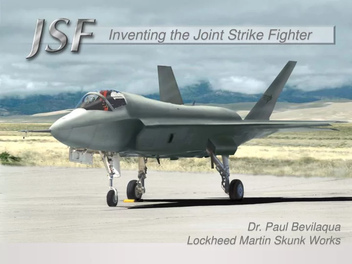
SLIDE 1 Inventing the Joint Strike Fighter
Lockheed Martin Skunk Works
SLIDE 2 General Arrangement
Length 50 ft Span 35 ft Wing area 450 sq ft Empty Weight 30,000 lbs AB Thrust 40,000 lbs Vertical Lift 40,000 lbs
DISTRIBUTION STATEMENT Approved for public release; distribution is unlimited.
SLIDE 3 Relative Size of Naval JSF
JSF1018010
Length 51 ft Span 43 ft Wing Area 620 ft Internal Fuel 19,500 lb Spot Factor 1.09 Length 47 ft Span 30 ft Wing Area 240 ft Internal Fuel 7,900 lb Spot Factor .82 Length 56 ft Span 37 ft Wing Area 400 ft Internal Fuel 10,800 lb Spot factor 1.0
2 2 2
DISTRIBUTION STATEMENT Approved for public release; distribution is unlimited.
SLIDE 4 Service Needs
609 − STOVL Strike Fighter to Replace the AV-8B and F/A-18C/D
150 − Supersonic STOVL Replacement for the Sea Harrier and GR-7
1763 − Stealthy Strike Fighter to Replace the F-16 and A-10
480 − Stealthy Strike Fighter
3000 US/UK Joint Strike Fighters
DISTRIBUTION STATEMENT A. Approved for public release; distribution is unlimited.
DISTRIBUTION STATEMENT Approved for public release; distribution is unlimited.
SLIDE 5 JSF Family of Aircraft
Length 51 ft Span 43 ft Wing Area 620 ft2 Internal fuel 19,500 lbs
Naval
Length 50 ft Span 35 ft Wing Area 460 ft2 Internal fuel 13,250 lbs
STOVL
Length 50 ft Span 35 ft Wing Area 460 ft2 Internal fuel 18,500 lbs
CTOL
DISTRIBUTION STATEMENT Approved for public release; distribution is unlimited.
SLIDE 6
JSF Commonality
SLIDE 7
Cousin Parts
SLIDE 8 Designed for Self Defense
360o Visibility AESA Long Range Radar Twin Verticals High T/ W Low Span Loading Low W / S High CL max 2 Internal AIM 120’s
DISTRIBUTION STATEMENT Approved for public release; distribution is unlimited.
SLIDE 9 Designed for Ground Attack
Low IR Signature Internal Precision Guided Weapons Agile Stable Target Tracking Good Field of View Low Vulnerability Supersonic Speeds Internal EO Systems
DISTRIBUTION STATEMENT Approved for public release; distribution is unlimited.
SLIDE 10 Designed for Low Vulnerability
Hot Parts Aft Fuel Tank Inerting Multiple Fuel Tanks Pilot Protection Dry Bay Fire Protection Jettisonable Weapons Multiple Load Paths Redundant Control Surfaces Air Start System
DISTRIBUTION STATEMENT Approved for public release; distribution is unlimited.
SLIDE 11 Designed for Maintainability
Integrated Subsystems Auxiliary Power Unit On Board Diagnostics Advanced Cockpit Self Contained Ladder OBOGS OBIGGS Benign Footprint Single Point Systems Check
DISTRIBUTION STATEMENT Approved for public release; distribution is unlimited.
SLIDE 12 F-16C F/A-18C
Sustained G’s
USAF USMC/RN USN
ADVANTAG E
Transonic Acceleration
F-16C USMC/RN USN USAF F/A-18C
Air to Air Combat Performance
F-16C F/A-18C USAF USMC/RN
Instantaneous G’s
USN
DISTRIBUTION STATEMENT Approved for public release; distribution is unlimited.
SLIDE 13 Naval F-35C Mission Performance
730 w/ Tanks
Mission Radius - nm
600
USN Profile: (2) 2K lb JDAM + (2) AIM-120
Opt M/Alt Cruise FLOT 400 nm Combat @ 35K ft Drop A-G Weapons
JSF
768
F/A-18C
329 927
2x 480 gal Tanks
547 3x 330 gal
Tanks
DISTRIBUTION STATEMENT For Official Use Only
SLIDE 14 USMC F-35B Mission Performance
Mission Radius - nm USMC Interdiction B: (2) 1K lb JDAM + (2) AIM-120
50 nm Opt M/Alt Cruise Ingress
FLOT
/Egress
Drop A-G Weapons
550 w/ Tanks 450
JSF
473 663
2x 480 gal Tanks
F/A-18C
375
Lot XIX w/ (2)1K JDAM+(2)AIM-120+(5)Pylons + Gun
AV-8B
273
2x 330 gal Tanks
504
DISTRIBUTION STATEMENT For Official Use Only
SLIDE 15
How We Won: The X - Planes
“Lockheed won by proposing a very innovative lift fan” - Boeing “Lift Fan Puts LockMart over the Top” - Aviation Week “Lift Fan Carries LM to Victory” - Interavia
SLIDE 16
Lift Fan Propulsion System
Lift Fan Clutch Fan Drive Shaft Roll Control Jets Thrust Vectoring Nozzle Cruise Engine
SLIDE 17
AV-8 Harrier Adopted by US Marine Corps 1970
SLIDE 18
The Harrier Approach Isn’t Supersonic
F-104 Starfighter
15,000 lbs Thrust Mach 2
AV-8B Harrier
20,000 lbs Thrust M < 1
SLIDE 19
Design Missions
SLIDE 20 Requirements Analysis
Willoughby Templates
SEGMENT NEED MISSION
SLIDE 21 VTOL Requirement Sizes the Engine
VTOL Design Point CTOL Design Point Sustained Turn Instantaneous Turn Transonic Acceleration STO VL 1.2 1.3 1.0 1.1 .8 .9 20 30 40 50 60 70 80 90
Wing Loading (WTO / S) Thrust to Weight Ratio (TSL / WTO )
SLIDE 22 Engine Requirements Analysis
Segment Need Feature
Short Take Off Wing Lift Jet Lift Vector Thrust Jet Flap High T/W Subsonic Cruise Low SFC Combat Mixed Flow High T/W Low IR Low BPR Low Drag High TSP Low SFC Variable Bypass Ratio High BPR Aft Nozzle Vertical Landing Reaction Control High T/W Low HGI Balance Cold Jets Supersonic Acceleration Thrust Transfer High BPR
SLIDE 23
The Basic Problem:
Not Enough Thrust, and It’s Too Far Aft
Weight, 30K lbs Thrust, 20K lbs
Goal
Weight, 30K lbs Thrust, 18K lbs Thrust, 18K lbs
Conventional F-16 “V/STOL” F-16
SLIDE 24 Weight, 30K lbs Thrust, 18K lbs Thrust, 18K lbs
Solving the Basic Problem
Not Enough Thrust, and It’s Too Far Aft Means to Extract Power
- Turbines
- Scoops
- Regeneration
- Heat Pipes
- Alternator
- Generator
- MHD
- EFD
Means to Transfer Power
- Shafts
- Ducts
- Heat Pipes
- Laser Beams
- Chain Drive
- Fiber Optics
- Wires
- Hydraulics
Means to Produce Thrust
- Fans
- Rockets
- Pulse Jets
- Ram Jets
- Ejectors
- Explosions
- MHD
- EFD
SLIDE 25 Shaft Driven Lift Fan Propulsion Concept
JSF119-611 Engine
JSF0419013
SLIDE 26 Shaft Driven Lift Fan Propulsion Concept
JSF119-611 Engine
JSF0419013
SLIDE 27 F-35 Propulsion System
JSF119-611 Engine
JSF0419013
SLIDE 28
Turboshaft Engine
Provides Shaft Power, but no Cruise Thrust
Turbofan Engine
Provides Cruise Thrust, but no Shaft Power
Alternative Types of Turbine Engine
SLIDE 29 Extracting Shaft Power
.
Open Closed
SLIDE 30 Comparison with LM Lift/Cruise System
at 40,000 lbs of thrust
2000 4000 6000 8000 10000 12000 14000 SDLF DL Engine Weight (lbs)
RCS Inlet Systems Nozzle Lift Fan Engine
SLIDE 31
Design Options
SLIDE 32
Number of Alternative Aircraft Is Too Large
SLIDE 33
Horizontal Stabilizer Assessment
SLIDE 34
Lift Fan Installation
SLIDE 35
JSF STOVL Propulsion System
SLIDE 36
AV-8B Harrier and the F-35 Musketeer
Fan Augmentation Hot Gases Aft Continuous Thrust Vectoring Lift Improvement Devices Poor Supersonic Area Distribution Overtemp Reduces Engine Life Water Injection Required Side by Side Jets Permit Hot Gas Ingestion Compressor Air for Reaction Control Jets Fan Augmentation Hot Gases Aft Continuous Thrust Vectoring Lift Improvement Devices Good Supersonic Area Distribution No Reduction of Engine Life No Water Injection Required Tandem Jets Prevent Hot Gas Ingestion Fan Air for Reaction Control Jets
SLIDE 37
Lockheed Martin Common Strike Fighter
STOVL CTOL
SLIDE 38
TFX: The Challenge of Joint Aircraft
USAF F-111 USN F-14 (F-111N)
SLIDE 39
Technology Assessment Contracts 1993 Lockheed Skunk Works
Shaft Driven Lift Fan $40M
McDonnell Douglas
Gas Driven Lift Fan $35M Demonstrate propulsion and airframe performance through ground test
SLIDE 40
McDonnell Douglas Gas Driven Lift Fan Concept 1993
SLIDE 41
Boeing Lift / Cruise Engine Concept
1994
Engine Nozzle
SLIDE 42
Lockheed Martin Large Scale Powered Model 1995
SLIDE 43
Lockheed Martin Large Scale Powered Model
NASA Testing
SLIDE 44
Boeing Large Scale Powered Model 1996
SLIDE 45 JSF Concept Demonstrator Awards
1996
Boeing X-32 Lift / Cruise Engine Lockheed Martin X-35 Shaft Driven Lift Fan
- Mature Technologies to Reduce Risk
- Build Aircraft to Validate Performance
- Refine the Design, as Necessary
SLIDE 46 JSF01070
- Build Two Aircraft, but Fly All Three Variants
- Fly the Production Configurations
- Demonstrate STOVL Performance and Supersonic Speed
- Prove Handling Qualities and Carrier Suitability
Lockheed Martin Demonstrator Approach
SLIDE 47
X-35 Commonality
X-35 Number 2 X-35 Number 1
Carrier X-35C CTOL X-35A STOVL X-35B
SLIDE 48 Lockheed Martin Aeronautics Company
Validation by High Fidelity Demonstrators
SLIDE 49 CTOL USAF Variant
- 27 Flights totaling 27.4 Hours over 30 Days
- LM, BAE SYSTEMS, MOD, and DOD Pilots Flew the X-35A
- “People were stunned” Gen Mike Hough, USMC
Lockheed Martin Aeronautics Company JSF0419027
SLIDE 50 Conversion to STOVL Variant
JSF0419030
SLIDE 51 Lockheed Martin Aeronautics Company JSF0419031
- Only Aircraft To Fly Supersonically, Hover, and Land Vertically in
the Same Flight
– Major Art Tomassetti, USMC, 20 July 2001
STOVL USMC / Royal Navy Variant
SLIDE 52
40,000 lbs of Vertical Lift from Just 4 Nozzles
48% 9% 43%
Lift Jet Characteristics
SLIDE 53
Infrared Lift Jet Visualization
SLIDE 54 Naval Variant Over Annapolis
DISTRIBUTION STATEMENT Approved for public release; distribution is unlimited.
Edwards Air Force Base
- 38 Flights in 33.2 Hours
- Use of a Side Stick Demonstrated
- Carrier Approaches Flown
Pax River Naval Air Station
- 33 Flights in 18.9 hours
- Carrier Landings Simulated
- Envelope Expanded to M = 1.2
First X-plane to fly across the US
- 2 Flights
- 5.9 Flight Hours
SLIDE 55
JSF STOVL Variants
32,000 lbs of Thrust 40,000 lbs of Thrust
SLIDE 56
What You See, Is What You Get!
SLIDE 57
2001 Collier Trophy
Awarded for " the greatest achievement in aeronautics or astronautics in America, demonstrated during the preceding year “ to the F-35 Lift Fan Propulsion System
SLIDE 58
Joint Strike Fighter - Economies of Scale
F-16 Falcon AV-8 Harrier F-18 Hornet A-10 Warthog
USAF 1765 USN 480 USMC 610 UK 150 FMS 3000 Total of 6000 aircraft Total of $200B
SLIDE 59 The Netherlands Italy Norway Denmark Canada Turkey U.K. Australia United States
International Coalition Investing in JSF
SLIDE 60
This is a Team Success