introduction
play

Introduction Location: Ashburn, VA 12 miles NW of Dulles - PowerPoint PPT Presentation

Belmont Executive Center, Building A Presentation Outline Introduction General Information Introduction Location: Ashburn, VA 12 miles NW of Dulles International Exiting Structural System Project Type: 5 Story, Multi-Tenant


  1. Belmont Executive Center, Building A Presentation Outline Introduction General Information Introduction • 
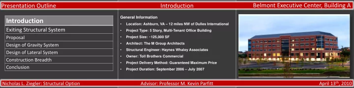
Location: Ashburn, VA – 12 miles NW of Dulles International Exiting Structural System • Project Type: 5 Story, Multi-Tenant Office Building • Proposal Project Size: ~125,000 SF • Architect: The M Group Architects Design of Gravity System • Structural Engineer: Haynes Whaley Associates Design of Lateral System • Owner: Toll Brothers Commercial Construction Breadth • Project Delivery Method: Guaranteed Maximum Price Conclusion • Project Duration: September 2006 – July 2007 April 13 th , 2010 Nicholas L. Ziegler: Structural Option Advisor: Professor M. Kevin Parfitt

  2. Belmont Executive Center, Building A Presentation Outline Existing Structural System Gravity System Introduction • 6 ¼” lightweight concrete on 3” composite metal deck, f’c = Exiting Structural System 3500 psi • Composite action achieved through the use of shear studs Proposal • W shape steel beams/columns Design of Gravity System • Square spread footings with perimeter strip footing, f’c = 4000 Design of Lateral System psi Construction Breadth • Typical bay sizes • 40’ - 0”x30’ - 0” exterior bays Conclusion • 26’ - 2”x30’ - 0” interior bays April 13 th , 2010 Nicholas L. Ziegler: Structural Option Advisor: Professor M. Kevin Parfitt

  3. Belmont Executive Center, Building A Presentation Outline Existing Structural System Lateral System Introduction • 4 braced frames • 3 in the North-South direction Exiting Structural System • 1 in East-West direction Proposal Design of Gravity System Design of Lateral System Construction Breadth Conclusion April 13 th , 2010 Nicholas L. Ziegler: Structural Option Advisor: Professor M. Kevin Parfitt

  4. Belmont Executive Center, Building A Presentation Outline Proposal Goals Introduction 1. Design structure using post-tensioned concrete 2. Maintain long exterior spans Exiting Structural System 3. Minimize the floor depth Proposal 4. Determine architectural impacts of new system 5. Compare cost and schedules of the original vs. the proposed Design of Gravity System system Design of Lateral System Solution Construction Breadth • Gravity System: One-way, post-tensioned slab supported by Conclusion wide, shallow post-tensioned girders • Lateral System: Concrete moment frames April 13 th , 2010 Nicholas L. Ziegler: Structural Option Advisor: Professor M. Kevin Parfitt

  5. Belmont Executive Center, Building A Presentation Outline Design of Gravity System Design of Post-Tensioned Slab Post-Tensioned Slab Design Parameters Introduction 1.0" Clear Cover Concrete Exiting Structural System • Normal weight concrete Size of Conventional Reinforcement #4 Bars • f‘c = 5000 psi Proposal Balanced Dead Load 50%-100% £ PT Tendons Design of Gravity System Precompression Stress ≤ 300psi ¥ • ½” Ø, 7 -wire strands Design of Lateral System Location of Tendon(s) Anchor ¼*L Ж £ To avoid extreme upward camber Construction Breadth ¥ To avoid cracking due to creep Conclusion Ж To avoid reinforcement congestion April 13 th , 2010 Nicholas L. Ziegler: Structural Option Advisor: Professor M. Kevin Parfitt

  6. Belmont Executive Center, Building A Presentation Outline Design of Gravity System Design of One-Way Post-Tensioned Slab Introduction Design Zones Exiting Structural System • Slab divided into different areas based on: 1 Proposal 1. Number of spans 2. Length of Spans Design of Gravity System 2 • 4 individual zones Design of Lateral System 3 4 Construction Breadth Conclusion April 13 th , 2010 Nicholas L. Ziegler: Structural Option Advisor: Professor M. Kevin Parfitt

  7. Belmont Executive Center, Building A Presentation Outline Design of Gravity System Design of One-Way Post-Tensioned Slab Introduction Design of Zone 2 Exiting Structural System • Introduce Normally Reinforced Concrete Beam • 18”x20” Proposal • f’c = 5000 psi Design of Gravity System • (5) #9’s – flexural reinforcement Design of Lateral System • (2) legs of #3 @ 8” – shear reinforcement Construction Breadth Conclusion April 13 th , 2010 Nicholas L. Ziegler: Structural Option Advisor: Professor M. Kevin Parfitt

  8. Belmont Executive Center, Building A Presentation Outline Design of Gravity System Design of One-Way Post-Tensioned Slab Introduction Design of Zone 2 Exiting Structural System • Live load reductions per ASCE 7-05 § 4.8 • Proposal Preliminary Size • L/45 – continuous spans: (30*12) / 45 → h = 8” Design of Gravity System • f’c = 5000 psi Design of Lateral System • Fe = 28.8 kips/ft (2 tendons per foot width) Construction Breadth • Increased span 2 tendon height at mid-distance due to Conclusion high tension stress at initial loading • (1) #4 per foot; T – over supports, B - midspan April 13 th , 2010 Nicholas L. Ziegler: Structural Option Advisor: Professor M. Kevin Parfitt

  9. Belmont Executive Center, Building A Presentation Outline Design of Gravity System Design of One-Way Post-Tensioned Slab Introduction Zone 1, 3, and 4 Exiting Structural System • Fe = 28.8 kips/ft in exterior bays • Proposal Fe = 20.9 kips/ft in interior bays • Tendon heights: Design of Gravity System • At supports: 7.0” Design of Lateral System • At mid- span: 1.0” Construction Breadth • Deflections were not an issue Conclusion • Max deflection = 0.53” in exterior spans • #4 @ 12” perpendicular to tendons for S&T April 13 th , 2010 Nicholas L. Ziegler: Structural Option Advisor: Professor M. Kevin Parfitt

  10. Belmont Executive Center, Building A Presentation Outline Design of Gravity System Design of Post-Tensioned Girders Introduction • Banded tendons to provide high PT force Exiting Structural System • 7 tendons per 2 ¾” conduit Proposal Method • Reduce tension at midspan in exterior bays by decreasing Design of Gravity System drape eccentricity in the middle span Design of Lateral System • Reduce bottom fiber tension at supports by decreasing Construction Breadth tendon height over columns Conclusion April 13 th , 2010 Nicholas L. Ziegler: Structural Option Advisor: Professor M. Kevin Parfitt

  11. Belmont Executive Center, Building A Presentation Outline Design of Gravity System Design of Post-Tensioned Girders Introduction Design of Typical Girder Exiting Structural System • Preliminary Size: 60” x 20” • Proposal PT force = 600 kips • Required number of tendons = 23 Design of Gravity System • Max deflection = 0.18” in exterior spans Design of Lateral System Construction Breadth Conclusion April 13 th , 2010 Nicholas L. Ziegler: Structural Option Advisor: Professor M. Kevin Parfitt

  12. Belmont Executive Center, Building A Presentation Outline Design of Gravity System Design of Post-Tensioned Girders Introduction Design of Girder Adjacent to Elevator Openings Exiting Structural System • Narrow cross section increased the precompression stress Proposal much greater than 300 psi • Extend tendon group entirely continuously through the girder Design of Gravity System • Provide tendons in exterior bays to balance dead load Design of Lateral System • Run off extra tendons through slab openings Construction Breadth • Required PT Force = 500/216/600 kips Conclusion • Required Number of Tendons = 19/9/23 • Maximum deflection in span 3 = 0.19” April 13 th , 2010 Nicholas L. Ziegler: Structural Option Advisor: Professor M. Kevin Parfitt

  13. Belmont Executive Center, Building A Presentation Outline Design of Lateral System Design of Concrete Moment Frames Introduction • 9 in north-south direction Exiting Structural System • 2 in east-west direction Proposal Deflection/Story Drift Limitations • L/400 – wind Design of Gravity System • 0.015*h sx – seismic Design of Lateral System ETABS Model Construction Breadth • Property Modifiers Conclusion • 0.70 – columns • 0.40 – beams April 13 th , 2010 Nicholas L. Ziegler: Structural Option Advisor: Professor M. Kevin Parfitt

  14. Belmont Executive Center, Building A Presentation Outline Design of Lateral System Design of Concrete Moment Frames Introduction Exiting Structural System Proposal Design of Gravity System Design of Lateral System Construction Breadth Conclusion • Torsion : Threshold 54.4 ft-kips, Tu = 25.3 ft-kips April 13 th , 2010 Nicholas L. Ziegler: Structural Option Advisor: Professor M. Kevin Parfitt

  15. Belmont Executive Center, Building A Presentation Outline Design of Lateral System Design of Typical Interior Column Introduction Exiting Structural System Proposal Design of Gravity System • Design of Lateral System Load Combination: 1.2D + 1.6W + L Construction Breadth Conclusion • Summary: f‘c = 6000 psi, As = (8) # 10’s → ρ = 1.76% ≤ 2.00% April 13 th , 2010 Nicholas L. Ziegler: Structural Option Advisor: Professor M. Kevin Parfitt

  16. Belmont Executive Center, Building A Presentation Outline Design of Gravity System Construction Management Breadth Introduction • Cost Comparison Exiting Structural System Proposal Design of Gravity System Design of Lateral System Construction Breadth Conclusion April 13 th , 2010 Nicholas L. Ziegler: Structural Option Advisor: Professor M. Kevin Parfitt

Download Presentation
Download Policy: The content available on the website is offered to you 'AS IS' for your personal information and use only. It cannot be commercialized, licensed, or distributed on other websites without prior consent from the author. To download a presentation, simply click this link. If you encounter any difficulties during the download process, it's possible that the publisher has removed the file from their server.

Recommend


More recommend