
Interfacing Processors and Peripherals
- I/O Design affected by many factors (expandability, resilience)
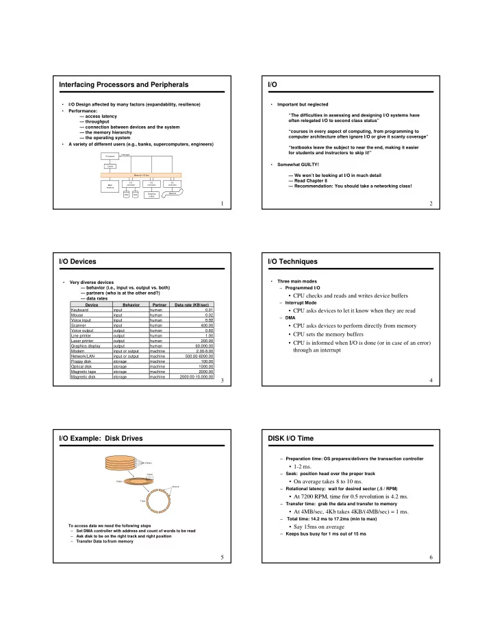
- Performance:
— access latency — throughput — connection between devices and the system — the memory hierarchy — the operating system f ff ( )
1
- A variety of different users (e.g., banks, supercomputers, engineers)
- utput
I/O
- Important but neglected
“The difficulties in assessing and designing I/O systems have
- ften relegated I/O to second class status”
“courses in every aspect of computing, from programming to computer architecture often ignore I/O or give it scanty coverage”
2
“textbooks leave the subject to near the end, making it easier for students and instructors to skip it!”
- Somewhat GUILTY!
— We won’t be looking at I/O in much detail — Read Chapter 8 — Recommendation: You should take a networking class!
I/O Devices
- Very diverse devices
— behavior (i.e., input vs. output vs. both) — partners (who is at the other end?) — data rates
Device Behavior Partner Data rate (KB/sec) Keyboard input human 0.01 Mouse input human 0.02 V i i t i t h 0 02
3
Voice input input human 0.02 Scanner input human 400.00 Voice output
- utput
human 0.60 Line printer
- utput
human 1.00 Laser printer
- utput
human 200.00 Graphics display
- utput
human 60,000.00 Modem input or output machine 2.00-8.00 Network/LAN input or output machine 500.00-6000.00 Floppy disk storage machine 100.00 Optical disk storage machine 1000.00 Magnetic tape storage machine 2000.00 Magnetic disk storage machine 2000.00-10,000.00
I/O Techniques
- Three main modes
– Programmed I/O
- CPU checks and reads and writes device buffers
– Interrupt Mode
- CPU asks devices to let it know when they are read
– DMA
4
- CPU asks devices to perform directly from memory
- CPU sets the memory buffers
- CPU is informed when I/O is done (or in case of an error)
through an interrupt
I/O Example: Disk Drives
Platter Platters Sectors Tracks5
To access data we need the following steps – Set DMA controller with address and count of words to be read – Ask disk to be on the right track and right position – Transfer Data to/from memory
TrackDISK I/O Time
– Preparation time: OS prepares/delivers the transaction controller
- 1-2 ms.
– Seek: position head over the proper track
- On average takes 8 to 10 ms.
– Rotational latency: wait for desired sector (.5 / RPM)
- At 7200 RPM time for 0 5 revolution is 4 2 ms
6
- At 7200 RPM, time for 0.5 revolution is 4.2 ms.
– Transfer time: grab the data and transfer to memory
- At 4MB/sec, 4Kb takes 4KB/(4MB/sec) = 1 ms.
– Total time: 14.2 ms to 17.2ms (min to max)
- Say 15ms on average
– Keeps bus busy for 1 ms out of 15 ms