insight power smart outlet mdr report
play

Insight Power Smart Outlet MDR Report Brendon Burke, Mark Chisholm, - PDF document

Insight Power Smart Outlet MDR Report Brendon Burke, Mark Chisholm, Garrett Olson, Kriss Strikis Advisor: David Irwin This report will discuss in detail several aspects of SDP Team 15s Project: The Insight Power Smart Outlet. In this report


  1. Insight Power Smart Outlet MDR Report Brendon Burke, Mark Chisholm, Garrett Olson, Kriss Strikis Advisor: David Irwin This report will discuss in detail several aspects of SDP Team 15’s Project: The Insight Power Smart Outlet. In this report we will discuss details including the specifications and requirements of the device, the responsibilities and expertise of the group members, and the current progress of the project. I. INTRODUCTION 
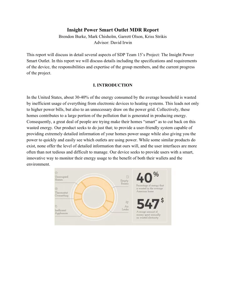
In the United States, about 30-40% of the energy consumed by the average household is wasted by inefficient usage of everything from electronic devices to heating systems. This leads not only to higher power bills, but also to an unnecessary draw on the power grid. Collectively, these homes contributes to a large portion of the pollution that is generated in producing energy. Consequently, a great deal of people are trying make their homes “smart” as to cut back on this wasted energy. Our product seeks to do just that; to provide a user-friendly system capable of providing extremely detailed information of your homes power usage while also giving you the power to quickly and easily see which outlets are using power. While some similar products do exist, none offer the level of detailed information that ours will, and the user interfaces are more often than not tedious and difficult to manage. Our device seeks to provide users with a smart, innovative way to monitor their energy usage to the benefit of both their wallets and the environment.

  2. System Specification Table Specification Value Device Weight < 1 lbs Device Dimensions ~ 4”-1”-1” (L-W-H) Target Cost of Manufacture ~ $50 Frequency of Power Sampling 1 second or less Outlet/Companion App Response Time 1 second or less Power Measurement Error < 1% II. OVERVIEW Block 1.A: Smart Meter Enclosure - High Voltage Side The first section of the design we will be looking at is the high voltage “side” of the Outlet itself. This part of the design is where the actual power sensing and third party device interaction will take place. We are using a simple voltage divider as well as a shunt resistor to obtain the information needed to calculate power. This information is fed into our off-the-shelf energy management IC, the Cirrus Logic CS5490, which uses this information to calculate various aspects of the power a device is drawing. Additionally, this part of the design includes a power relay, to allow the outlet to essentially cut power to devices plugged into it. The results of

  3. this block can be easily tested by comparing the output to the power usage specifications of a given device. The voltage input pins on the CS5490 accept a differential analog input with a maximum peak voltage of 250 mV when using the default gain of 10. The minimum and maximum common mode voltages accepted are -250mV and VDDA (3.3V). The manufacturer does not specify input resistance or maximum allowable current across these pins but the provided application notes recommend using a 1 kohm resistor on one input pin. To provide the voltage signal we use a voltage divider, targeting an output signal peak of 100mV. For a 120V RMS input, actual peak input is 120V*√2 ≅ 170V. Thus, to divide this signal to 100mV, we choose R1 = 1700*R2. Actual values used are 1.74 Mohm and 1 kohm. To satisfy the common mode voltage range requirement we ensure that the energy measurement IC power supply is referenced to the neutral line of the input voltage. The CS5490 accepts a current input signal from a variety of sensor types, but for size and reliability we choose to use a shunt resistor. The current input pins have very similar specifications to the voltage pins. To choose a shunt resistor value, we target an output signal peak of 100 mV. With an expected maximum current of 10 A, the corresponding resistor size is 0.01 ohm and is chosen as such. To limit the current through the input pins, the manufacturer's application notes suggest a 1 kohm resistor on each input pin. To satisfy the common mode voltage requirement we place one end of the shunt resistor on the common ground on the neutral line. Block 1.B: Smart Meter Enclosure - Low Voltage Side We have included an optocoupler in our design to isolate the Data Analysis and Control portion of the design from the potentially high current coming from rest of the device. Within this block, we use a Raspberry PI 3B. This part of the design is where all of the “heavy” work is done. This is where our Classification Algorithm will be running to continuously analyze the power date fed to it by the Cirrus IC.This will also be the point of communication between the outlet and the Companion App, sending data to the app as well as receiving and interpreting commands from the app. Block 2: User Interface The last block of the design is the user interface for the system we are designing. This will take the form of an Android app, written in Java in android studio. The app will provide a simple, but intuitive interface that will allow users to monitor power usage data from multiple outlets in real time. It will also provide users with the ability to control the outlet by turning it on and off and setting schedules and protocols for certains types of devices,

  4. III. PROJECT MANAGEMENT Table of Project MDR Goals Goal Status Device/App Response Time < 1 second Completed Power Measurement Within 1% On-Going (Testing Phase) App Graph Implemented Completed Power Data Samples Every 1 second Completed Within the first half of SDP our team has been able accomplish most of the goals we set out to reach by now. Our app and device both have a response time that is within our 1 second specification; the app is able to easily graph in real time the data that it is receiving from the outlet, and our device samples the power data every second. The only goal that we did not fully achieve was the power measurement itself; however, this is due to some unknowns in the values we are receiving from our benchmark (Kill-A-Watt). Moving forward, we will be using the actual power consumption specifications of a given device in order to test the accuracy of our data. Thus far, our group has been able to effectively divide the work. Kriss has been spearheading hardware development, with the help of Garrett and Mark. Brendon and Garrett have been implementing the companion app, as well as establishing a wireless connection between the app and device. Mark has been assisting in both areas while researching how to implement our classification algorithm using SciKit Learn.

  5. IV. CONCLUSION Overall, we are about at the stage in our project that we hoped to be by this point. We have the “core” functionality of the device (power sensing) developed and our app is a simple but easy to read interface. Moving forward, we will be moving up to full voltage AC and ensuring our power readings continue to be accurate at higher power. We also will be implementing our classification algorithm so that the device can use the power data to provide useful information. We expect some difficulty when networking various outlets and the app, as we discovered while working on the initial app there are some compatibility issues with android and python. Over the course of winter break and next semester we hope to have at least 3 fully functional outlets prepared for our final demo, where we will show the devices ability to distinguish between different types of devices. ACKNOWLEDGMENTS We would like to give a special thank you to our advisor David Irwin for the time and effort he has dedicated to helping us bring this project to life. We would also like to thank Shira Epstein and the staff of M5 for all the help and resources they provided to us throughout the process. Finally, we’d like to thank Professors Hollot and Soules for helping to keep us organized and on track throughout SDP.

Download Presentation
Download Policy: The content available on the website is offered to you 'AS IS' for your personal information and use only. It cannot be commercialized, licensed, or distributed on other websites without prior consent from the author. To download a presentation, simply click this link. If you encounter any difficulties during the download process, it's possible that the publisher has removed the file from their server.

Recommend


More recommend