Impact of Level 1 Radiometric Stability on Level 2 Products and - - PowerPoint PPT Presentation

impact of level 1 radiometric stability on level 2
SMART_READER_LITE
LIVE PREVIEW

Impact of Level 1 Radiometric Stability on Level 2 Products and - - PowerPoint PPT Presentation

National Aeronautics and Space Administration Jet Propulsion Laboratory California Institute of Technology Pasadena, California Impact of Level 1 Radiometric Stability on Level 2 Products and Expectations for CrIS on NPOESS NASA Sounder


slide-1
SLIDE 1

National Aeronautics and Space Administration Jet Propulsion Laboratory California Institute of Technology Pasadena, California

1

Impact of Level 1 Radiometric Stability on Level 2 Products and Expectations for CrIS on NPOESS NASA Sounder Science Team Meeting

  • T. Pagano, Evan Manning

May 4, 2009

slide-2
SLIDE 2

National Aeronautics and Space Administration Jet Propulsion Laboratory California Institute of Technology Pasadena, California

Introduction

  • AIRS Team has high interest in CrIS for continuing AIRS

measurements

  • Government and Industry teams actively working

towards product development. Thanks for your hard work!

  • NASA to evaluate products from IPO and NOAA
  • Expect good performance overall with a few exceptions
  • This talk focuses on impact of low emissivity Internal

Calibration Target (ICT) on Level 2

  • Small impact (< 0.2K) instability to L2 products
  • Should be OK for process studies, may affect climate

studies

2

slide-3
SLIDE 3

National Aeronautics and Space Administration Jet Propulsion Laboratory California Institute of Technology Pasadena, California

3

AIRS, CrIS, and IASI have Similar Features

METOP NPOESS

Aqua

AIRS CrIS IASI

Spectral Range (cm-1) 650-1140 650-1095 645-2760 1210-1610 1210-1750 2170-2675 2155-2550 Spectral Resolution (cm-1) 0.4-2.1 0.625-2.5 (Unapodized)* 0.35-0.5 Spatial Resolution 14 km 14 km 12 km IFOV 3x3/1.1° 3x3/1.1° 2x2/1.1° Size 0.9 m3 0.5 m3 1.7 m3 Mass 177 kg 165 kg 236 kg Power 256 W 135 W 210 W Orbit Crossing Time 1:30 am/pm 1:30 am/pm 9:30 am/pm

AIRS CrIS IASI *Note: Unapodized Resolution about 2X lower than Apodized

slide-4
SLIDE 4

National Aeronautics and Space Administration Jet Propulsion Laboratory California Institute of Technology Pasadena, California

CrIS Internal Calibration Target (ICT) is Diffuse Cavity Design

4

Old ICT Environmental Model Used in SDR Algorithm Version 2.13

ICT Cavity SSM Baffle OMA Housing & Frame IFM Beam Splitter

8.8º 13.1º 28.7º

( )

σ ε surf ( )

σ ε BS

( )

σ εOMA

( )

σ εbaffle

( )

σ ε eff

ICT

T

OMA

T

baffle

T

BS

T

SSM Baffle, OMA Housing & IFM Beam Splitter Radiate Energy Into ICT Cavity A Portion of that Energy Is Reflected Back to Interferometer

1.7º

Central Obscuration

Half angles represent approximate view to external environment

From ITT SDR Algorithm (version 2.17)l Updates.ppt

slide-5
SLIDE 5

National Aeronautics and Space Administration Jet Propulsion Laboratory California Institute of Technology Pasadena, California

AIRS On-Board Calibrator Blackbody (OBC) is Wedge Design

5 AIRS Scan Geometry

  • OBC Blackbody (OBC)
  • T = 307.9K
  • ε > 0.998
  • T_precision = 0.01K
slide-6
SLIDE 6

National Aeronautics and Space Administration Jet Propulsion Laboratory California Institute of Technology Pasadena, California

Comparison of AIRS and CrIS on-board blackbody “Effective” Emissivities

6

slide-7
SLIDE 7

National Aeronautics and Space Administration Jet Propulsion Laboratory California Institute of Technology Pasadena, California

Observed Radiance is sum of Emitted and Reflected Components Variance on observed radiance from the ICT Background is sum over contribution from all elements Variance on background has three components: Area, emissivity and temperature Since it is impossible to differentiate between these, define “effective” temperature error to match observed stability in the laboratory

Uncertainty on Emitted Radiance Treated as “Effective” Temperature Uncertainty of Background

7

BKG ICT ICT

  • bs

L P L ) 1 ( ε ε − + =

2 2 2 2 2 2 2

) 1 ( ) (

BKG ICT ICT BKG ICT ICT ICT

  • bs

L L P P L δ ε δε δ ε δ − + − + =

∑ ∑

≡ =

i i i i i i i i BKG

T P A T P A L ) ( ' ) ( ε ε

∑ ∑ ∑

+ + =

i i i i i i i i i i i i i BKG

T dT T dP A T P A T P A L

2 2 2 2 2 2 2 2 2 2 2

) ( ' ) ( ' ) ( ' δ ε ε δ ε δ δ

2 _ 2 2 2 _

) (

BKG eff BKG BKG

  • bs

BKG

T dT T dP L δ ε δ =

slide-8
SLIDE 8

National Aeronautics and Space Administration Jet Propulsion Laboratory California Institute of Technology Pasadena, California

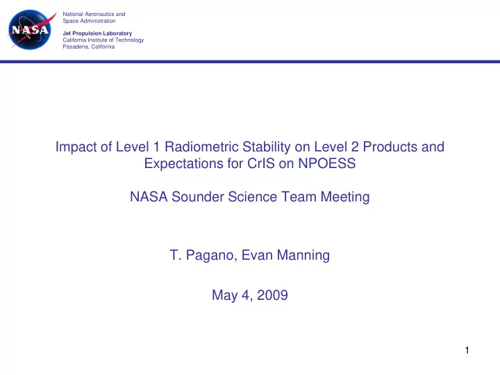
5K Fluctuation in Baffle Temperature Calculated, 0.75K Uncertainty Claimed

8

Delta T Between ICT View of Baffle Average and Temperature Sensor Location

  • 5
  • 4
  • 3
  • 2
  • 1

1 2 1000 2000 3000 4000 5000 6000 7000 Orbit Time (Second) Delta T (C) Beta 12 Hot, EOL Properties Beta 28 Hot, Scanning Mirror EOL Beta 28 Hot, Variable Erath IR Spacecraft Thermal Control Handbook (Case 5) Beta 28Hot, Scanning Mirror, 2-sigma average cold/hot variation (Case 3) Delta Baffle Correction to be applied

Realistic Orbital Parameter Variations Results in 0.75 C Uncertainty in Predicted Average Baffle Temperature Knowledge

Correct ion t o be applied t o t he baffle t emperat ure Variat ions from t he correct ion profile represent errors

From ITT SDR Algorithm (version 2.17)l Updates.ppt

slide-9
SLIDE 9

National Aeronautics and Space Administration Jet Propulsion Laboratory California Institute of Technology Pasadena, California

5K “Effective” Background Temperature required to match observed difference during TVAC testing?

9

  • D. Jordan, L. Woody, D. Gregory, R. Hertel, R. Frain, L. Suwinski, CrIS FM1 Tech memo 8231508

– Radiometric Uncertainty and Long Term Radiometric Stability, December 17, 2008 CrIS Obs: Difference between

  • bserved radiance calculated

using SDR algorithm and ECT radiance during Radiometric Confidence Test (Jordan memo) CrIS Reported: ICT Radiance Knowledge (Jordan memo) CrIS Accuracy Spec CrIS Calculated (JPL). δTeff_BKG = 5K

slide-10
SLIDE 10

National Aeronautics and Space Administration Jet Propulsion Laboratory California Institute of Technology Pasadena, California

Broken down and compared to AIRS with comparable uncertainty.

10

Table 1. Comparison of Temperatures, Emissivities and Uncertainties for CrIS and AIRS

Parameter CrIS AIRS ICT Temp (K) 287 307.9 ICT Temp Uncty (K) 0.037 0.026 ICT Emis ~0.975 ~0.998 ICT Emis Uncty 0.01 0.004 Bkg Emis 0.95 1 Bkg Emis Uncty 0.05 Bkg Temp (K) 284 252.12 Bkg Temp Uncty (K) 5 5

slide-11
SLIDE 11

National Aeronautics and Space Administration Jet Propulsion Laboratory California Institute of Technology Pasadena, California

Sanity check for uncertainty calculation about right

11 CrIS Reflected Energy CrIS ICT Residual (All terms) 100% of AIRS Energy Assumed Uncorrected 10% of Reflected Energy

slide-12
SLIDE 12

National Aeronautics and Space Administration Jet Propulsion Laboratory California Institute of Technology Pasadena, California

  • CrIS. Only 5K Error Assumed in Error
  • AIRS. All Reflected Energy Included in Error

Expect 50-200 mK Uncorrected Radiance from CrIS

12

dT T dP T L

BKG BKG eff ICT BKG

  • bs

) ( ) 1 (

_ _

δ ε δ − = ) ( ) 1 (

_ _ BKG eff OBC BKG

  • bs

T P L ε δ − =

slide-13
SLIDE 13

National Aeronautics and Space Administration Jet Propulsion Laboratory California Institute of Technology Pasadena, California

13

AIRS Radiometric Uncertainty Estimate at 265K

Based on Pre-Flight Calibration at 265K

0.07K (1σ Average + 40 mK Other)

slide-14
SLIDE 14

National Aeronautics and Space Administration Jet Propulsion Laboratory California Institute of Technology Pasadena, California

14

Expect Orbital and Seasonal Dependence to Residual

[ ]

summer in max in winter, Minimum side day equator at maximum side, night equator at Minimum year 1 ,

  • rbit

1 / 1 ICT

  • ff

radiance Reflected

  • f

Component ed Uncorrect ) 2 cos( ) 2 cos( ) (

2 1 2 , 1 max _ _ 2 2 1 1 max _ _ _

= = = = + + + = φ φ δ φ π φ π δ δ f L t f t f L t L

BKG

  • bs

BKG

  • bs

BKG

  • bs
slide-15
SLIDE 15

National Aeronautics and Space Administration Jet Propulsion Laboratory California Institute of Technology Pasadena, California

Impact of Radiance Instability on Level 2 Product: Temperature at 100 mb

15

slide-16
SLIDE 16

National Aeronautics and Space Administration Jet Propulsion Laboratory California Institute of Technology Pasadena, California

Impact of Radiance Instability on Level 2 Product: Surface Air Temperature

16

slide-17
SLIDE 17

National Aeronautics and Space Administration Jet Propulsion Laboratory California Institute of Technology Pasadena, California

Summary and Conclusions

  • Internal Calibration Target (ICT) Blackbody on CrIS on NPP does

not meet emissivity specifications

  • View to external baffles will introduce reflected energy contribution

to calibration radiance viewed by CrIS

  • Energy will modulate with instrument temperature
  • Correction algorithm will be applied. It’s a matter of how well this

can be done.

  • Expect residuals on the order of 50-200 mK
  • May be OK for process studies, but may affect ability to trend

products over time

  • Will impact Level 2 product temperatures with similar errors unless it

can be tuned out using earth observations

  • Fix to ICT requested for FM2
  • Again, Thanks to the CrIS Team for all their efforts.

17